

Answered step by step
Verified Expert Solution
Question
1 Approved Answer
Please help with C# code! Part A Design the main form for the Circuit Analyzer. Use the images provided with the requirements document. Place a
Please help with C# code!
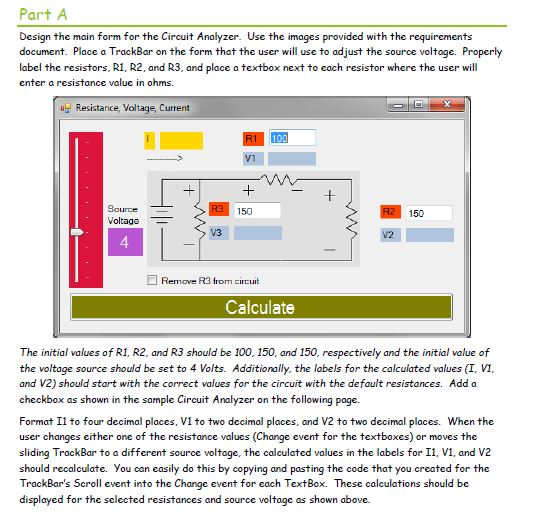
Part A Design the main form for the Circuit Analyzer. Use the images provided with the requirements document. Place a TrackBar on the form that the user will use to adjust the source voltage. Properly label the resistors, R1, R2, and R3, and place a textbox next to each resistor where the user will enter a resistance value in ohms. Resistance, Voltage, Current Bource Voltage 150 150 V3 4 Remove R3 from circuit Calculate The initial values of R1, R2, and R3 should be 100, 150, and 150, respectively and the initial value of the voltage source should be set to 4 Volts. Additionally, the labels for the calculated values (I, VI, and V2) should start with the correct values for the circuit with the default resistances. Add a checkbox as shown in the sample Circuit Analyzer on the following page. Format Il to four decimal places, V1 to two decimal places, and V2 to two decimal places. When the user changes either one of the resistance values (Change event for the textboxes) or moves the sliding TrackBar to a different source voltage, the calculated values in the labels for I1, V1, and V2 TrackBar's Scroll event into the Change event for each TextBox. These calculations should be displayed for the selected resistances and source voltage as shown above. Part A Design the main form for the Circuit Analyzer. Use the images provided with the requirements document. Place a TrackBar on the form that the user will use to adjust the source voltage. Properly label the resistors, R1, R2, and R3, and place a textbox next to each resistor where the user will enter a resistance value in ohms. Resistance, Voltage, Current Bource Voltage 150 150 V3 4 Remove R3 from circuit Calculate The initial values of R1, R2, and R3 should be 100, 150, and 150, respectively and the initial value of the voltage source should be set to 4 Volts. Additionally, the labels for the calculated values (I, VI, and V2) should start with the correct values for the circuit with the default resistances. Add a checkbox as shown in the sample Circuit Analyzer on the following page. Format Il to four decimal places, V1 to two decimal places, and V2 to two decimal places. When the user changes either one of the resistance values (Change event for the textboxes) or moves the sliding TrackBar to a different source voltage, the calculated values in the labels for I1, V1, and V2 TrackBar's Scroll event into the Change event for each TextBox. These calculations should be displayed for the selected resistances and source voltage as shown aboveStep by Step Solution
There are 3 Steps involved in it
Step: 1

Get Instant Access to Expert-Tailored Solutions
See step-by-step solutions with expert insights and AI powered tools for academic success
Step: 2

Step: 3
Ace Your Homework with AI
Get the answers you need in no time with our AI-driven, step-by-step assistance
Get Started
Programming The Perl DBI Database Programming With Perl
Authors: Tim Bunce, Alligator Descartes
1st Edition
1565926994, 978-1565926998