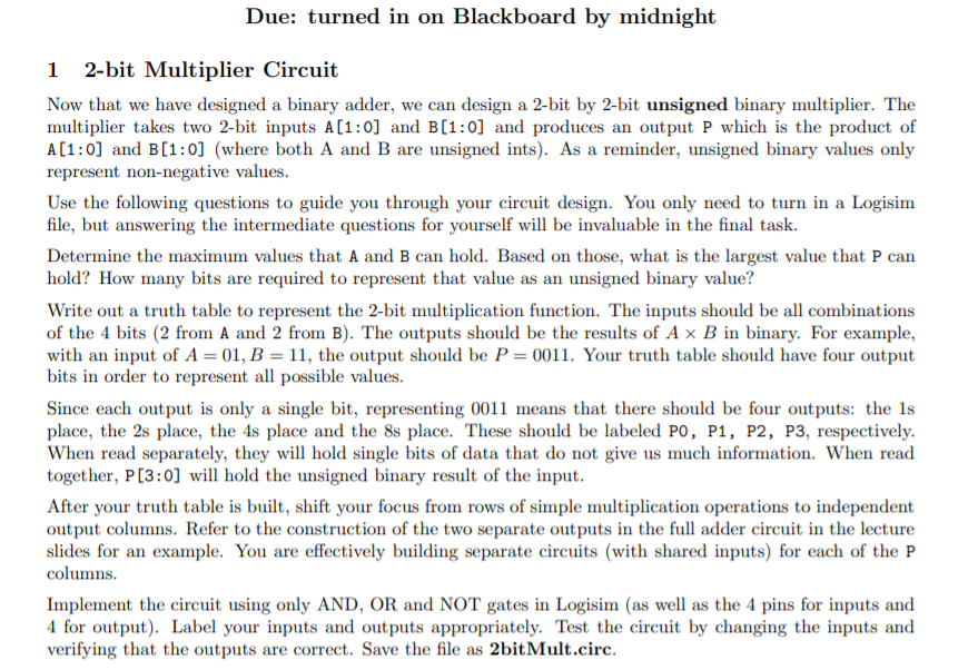
Question: ***Please make a circuit only using and or not I use program Logisim this is comp org Due: turned in on Blackboard by midnight 1

***Please make a circuit only using and or not
I use program Logisim
this is comp org
Due: turned in on Blackboard by midnight 1 2-bit Multiplier Circuit Now that we have designed a binary adder, we can design a 2-bit by 2-bit unsigned binary multiplier. The multiplier takes two 2-bit inputs A [1:0) and B(1:0) and produces an output P which is the product of A[1:0] and B(1:0) (where both A and B are unsigned ints). As a reminder, unsigned binary values only represent non-negative values. Use the following questions to guide you through your circuit design. You only need to turn in a Logisim file, but answering the intermediate questions for yourself will be invaluable in the final task. Determine the maximum values that A and B can hold. Based on those, what is the largest value that P can hold? How many bits are required to represent that value as an unsigned binary value? Write out a truth table to represent the 2-bit multiplication function. The inputs should be all combinations of the 4 bits (2 from A and 2 from B). The outputs should be the results of A x B in binary. For example, with an input of A = 01, B = 11, the output should be P=0011. Your truth table should have four output bits in order to represent all possible values. Since each output is only a single bit, representing 0011 means that there should be four outputs: the 1s place, the 2s place, the 4s place and the 8s place. These should be labeled PO, P1, P2, P3, respectively. When read separately, they will hold single bits of data that do not give us much information. When read together, P(3:0) will hold the unsigned binary result of the input. After your truth table is built, shift your focus from rows of simple multiplication operations to independent output columns. Refer to the construction of the two separate outputs in the full adder circuit in the lecture slides for an example. You are effectively building separate circuits (with shared inputs) for each of the P columns. Implement the circuit using only AND, OR and NOT gates in Logisim (as well as the 4 pins for inputs and 4 for output). Label your inputs and outputs appropriately. Test the circuit by changing the inputs and verifying that the outputs are correct. Save the file as 2bitMult.circ. Due: turned in on Blackboard by midnight 1 2-bit Multiplier Circuit Now that we have designed a binary adder, we can design a 2-bit by 2-bit unsigned binary multiplier. The multiplier takes two 2-bit inputs A [1:0) and B(1:0) and produces an output P which is the product of A[1:0] and B(1:0) (where both A and B are unsigned ints). As a reminder, unsigned binary values only represent non-negative values. Use the following questions to guide you through your circuit design. You only need to turn in a Logisim file, but answering the intermediate questions for yourself will be invaluable in the final task. Determine the maximum values that A and B can hold. Based on those, what is the largest value that P can hold? How many bits are required to represent that value as an unsigned binary value? Write out a truth table to represent the 2-bit multiplication function. The inputs should be all combinations of the 4 bits (2 from A and 2 from B). The outputs should be the results of A x B in binary. For example, with an input of A = 01, B = 11, the output should be P=0011. Your truth table should have four output bits in order to represent all possible values. Since each output is only a single bit, representing 0011 means that there should be four outputs: the 1s place, the 2s place, the 4s place and the 8s place. These should be labeled PO, P1, P2, P3, respectively. When read separately, they will hold single bits of data that do not give us much information. When read together, P(3:0) will hold the unsigned binary result of the input. After your truth table is built, shift your focus from rows of simple multiplication operations to independent output columns. Refer to the construction of the two separate outputs in the full adder circuit in the lecture slides for an example. You are effectively building separate circuits (with shared inputs) for each of the P columns. Implement the circuit using only AND, OR and NOT gates in Logisim (as well as the 4 pins for inputs and 4 for output). Label your inputs and outputs appropriately. Test the circuit by changing the inputs and verifying that the outputs are correct. Save the file as 2bitMult.circ
Step by Step Solution
There are 3 Steps involved in it

Get step-by-step solutions from verified subject matter experts


