Answered step by step
Verified Expert Solution
Question
1 Approved Answer
Please provide the code, not just explanation. I have STM32G031K8 . Please provide the code, not just explanation. I have STM32G031K8 . Problem 3. In
Please provide the code, not just explanation. I have STM32G031K8 .
Please provide the code, not just explanation. I have STM32G031K8 .
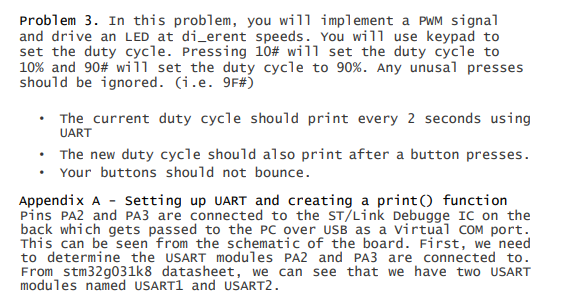
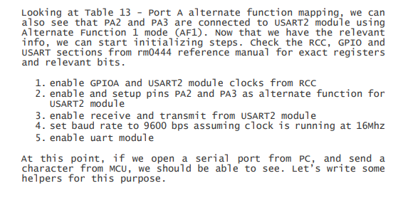
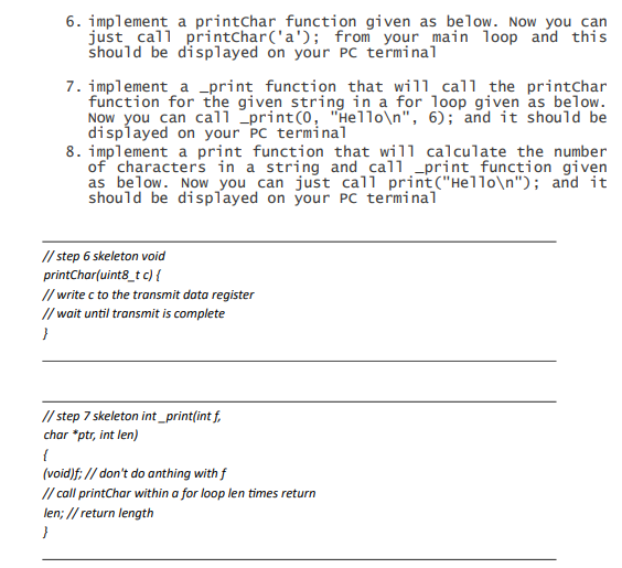
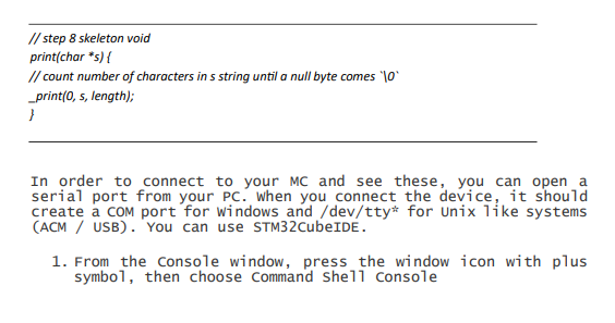
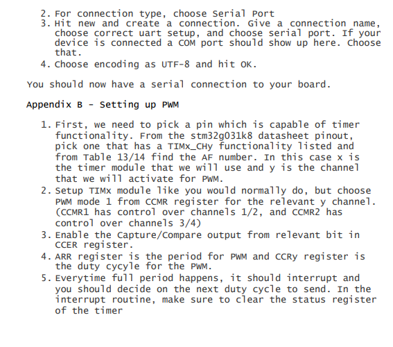
Problem 3. In this problem, you will implement a PWM signal and drive an LED at di_erent speeds. You will use keypad to set the duty cycle. Pressing 10# will set the duty cycle to 10% and 90# wi 11 set the duty cycle to 90%. Any unusal presses should be ignored. (i.e. 9F\#) - The current duty cycle should print every 2 seconds using UART - The new duty cycle should also print after a button presses. - Your buttons should not bounce. Appendix A - setting up UART and creating a print() function Pins PA2 and PA3 are connected to the ST/Link Debugge IC on the back which gets passed to the PC over USB as a Virtual COM port. This can be seen from the schematic of the board. First, we need to determine the USART modules PA2 and PA3 are connected to. From stm 32g031k8 datasheet, we can see that we have two USART modules named USART1 and USART2. Looking at Table 13 - Port A alternate function mapping, we can a1so see that PA2 and PA3 are connected to USART2 module using Alternate Function 1 mode (AF1). Now that we have the relevant info, we can start initializing steps. Check the RCC, GPIO and USART sections from rm0444 reference manual for exact registers and relevant bits. 1. enable GPIOA and USART2 module clocks from RCC 2. enable and setup pins PA2 and PA3 as a1ternate function for USART2 module 3. enable receive and transmit from USART2 module 4. set baud rate to 9600 bps assuming clock is running at 16Mhz 5. enable uart module At this point, if we open a serial port from PC, and send a character from MCU, we should be able to see. Let's write some helpers for this purpose. 6. implement a printchar function given as below. Now you can just call printChar('a'); from your main loop and this should be displayed on your PC terminal 7. implement a _print function that will call the printchar function for the given string in a for loop given as below. Now you can ca11 _print (0, "He11o ",6); and it should be displayed on your PC termina1 8. implement a print function that will calculate the number of characters in a string and call print function given as below. Now you can just ca11 print ("Hello "); and it should be displayed on your PC terminal In order to connect to your MC and see these, you can open a serial port from your PC. When you connect the device, it should create a com port for windows and/dev/tty for Unix like systems (ACM / USB). You can use STM32CubeIDE. 1. From the console window, press the window icon with plus symbo1, then choose Command She 11 Console 2. For connection type, choose Serial Port 3. Hit new and create a connection. Give a connection name, choose correct uart setup, and choose serial port. If your device is connected a com port should show up here. Choose that. 4. Choose encoding as UTF-8 and hit OK. You should now have a serial connection to your board. Appendix B - Setting up PWM 1. First, we need to pick a pin which is capable of timer functionality. From the stm32g031k8 datasheet pinout, pick one that has a TIMx_CHy functionality listed and from Table 13/14 find the AF number. In this case x is the timer module that we will use and y is the channel that we will activate for PWM. 2. Setup TIMX module like you would normally do, but choose PWM mode 1 from CCMR register for the relevant y channe1. (CCMR1 has control over channels 1/2, and CCMR2 has control over channels 3/4) 3. Enable the Capture/Compare output from relevant bit in CCER register. 4. ARR register is the period for PWM and CCRy register is the duty cycyle for the PWM. 5. Everytime full period happens, it should interrupt and you should decide on the next duty cycle to send. In the interrupt routine, make sure to clear the status register of the timerStep by Step Solution
There are 3 Steps involved in it
Step: 1

Get Instant Access to Expert-Tailored Solutions
See step-by-step solutions with expert insights and AI powered tools for academic success
Step: 2

Step: 3

Ace Your Homework with AI
Get the answers you need in no time with our AI-driven, step-by-step assistance
Get Started


