
 please solve this quastion on quartus program
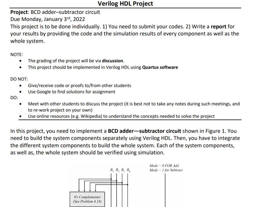
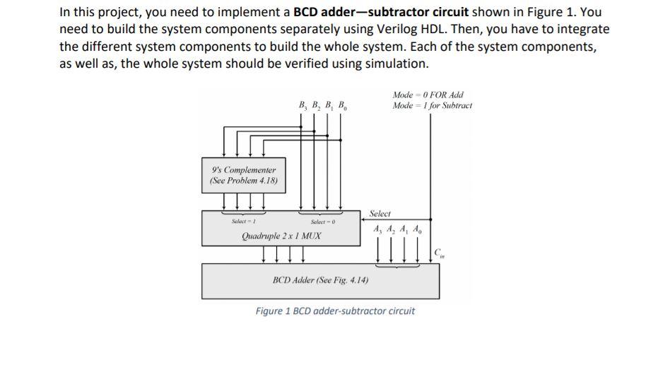
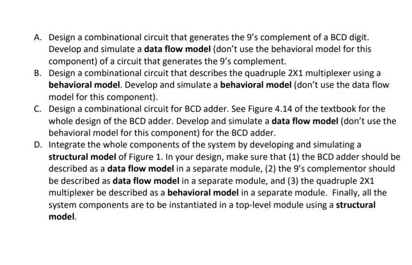
Verilog HDL Project Project: BCD adder-subtractor circuit Due Monday, January 3rd, 2022 This project is to be done individually. 1) You need to submit your codes. 2) Write a report for your results by providing the code and the simulation results of every component as well as the whole system. NOTE: The grading of the project will be via discussion. This project should be implemented in Verilog HDL using Quartus software DO NOT: Give/receive code or proofs to/from other students Use Google to find solutions for assignment DO: Meet with other students to discuss the project (it is best not to take any notes during such meetings, and to re-work project on your own) Use online resources (e.g. Wikipedia) to understand the concepts needed to solve the project In this project, you need to implement a BCD adder-subtractor circuit shown in Figure 1. You need to build the system components separately using Verilog HDL. Then, you have to integrate the different system components to build the whole system. Each of the system components, as well as, the whole system should be verified using simulation. B, B, B, B, Mode 0 FOR Add Mode = 1 for Subtract 9's Complementer (See Problem 4.78) In this project, you need to implement a BCD adder-subtractor circuit shown in Figure 1. You need to build the system components separately using Verilog HDL. Then, you have to integrate the different system components to build the whole system. Each of the system components, as well as, the whole system should be verified using simulation. B, B, B, B, Mode - 0 FOR Add Mode=1 for Subtract 9's Complementer (See Problem 4.18) Select Select Select- Quadruple 2 x / MUX in BCD Adder (See Fig. 4.14) Figure 1 BCD adder-subtractor circuit A. Design a combinational circuit that generates the 9's complement of a BCD digit. Develop and simulate a data flow model (don't use the behavioral model for this component) of a circuit that generates the 9's complement. B. Design a combinational circuit that describes the quadruple 2x1 multiplexer using a behavioral model. Develop and simulate a behavioral model (don't use the data flow model for this component). C. Design a combinational circuit for BCD adder. See Figure 4.14 of the textbook for the whole design of the BCD adder. Develop and simulate a data flow model (don't use the behavioral model for this component) for the BCD adder. D. Integrate the whole components of the system by developing and simulating a structural model of Figure 1. In your design, make sure that (1) the BCD adder should be described as a data flow model in a separate module, (2) the 9's complementor should be described as data flow model in a separate module, and (3) the quadruple 2X1 multiplexer be described as a behavioral model in a separate module. Finally, all the system components are to be instantiated in a top-level module using a structural model


 please solve this quastion on quartus program


