Answered step by step
Verified Expert Solution
Question
1 Approved Answer
Please solve this question with clear steps.And.Check the answers or make sure that they are right. Image transcription text 4 QUESTION 4 (40 Points) Using
Please solve this question with clear steps.And.Check the answers or make sure that they are right.

Image transcription text
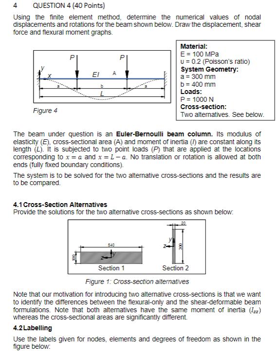
4 QUESTION 4 (40 Points) Using the finite element method, determine the numerical values of nodaldisplacements and rotations for the beam shown below. Draw the displacement, shear force and
flexural moment graphs. Material: P P E = 100 MPa U = 0.2 (Poisson's ratio) FI A System G...

Image transcription text
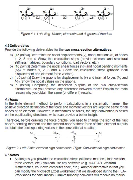
12 10 Figure 4.1: Labelling: Nodes, elements and degrees of freedom 4.3 Deliverables Provide thefollowing deliverables for the two cross-section alternatives. a) [15 points] Determine the nodal
displacements (V), nodal rotations (0) at nodes 1, 2, 3 and 4. Show the calculation steps (p...
4 QUESTION 4 (40 Points) Using the finite element method, determine the numerical values of nodal displacements and rotations for the beam shown below. Draw the displacement, shear force and flexural moment graphs. Material: E = 100 MPa P U 0.2 (Poisson's ratio) Figure 4 A b System Geometry: a = 300 mm b = 400 mm Loads: P = 1000 N Cross-section: Two alternatives. See below. The beam under question is an Euler-Bernoulli beam column. Its modulus of elasticity (E), cross-sectional area (A) and moment of inertia (/) are constant along its length (L). It is subjected to two point loads (P) that are applied at the locations corresponding to x = a and x = L-a. No translation or rotation is allowed at both ends (fully fixed boundary conditions). The system is to be solved for the two alternative cross-sections and the results are to be compared. 4.1 Cross-Section Alternatives Provide the solutions for the two alternative cross-sections as shown below: 540 Section 1 20 Section 2 Figure 1: Cross-section alternatives Note that our motivation for introducing two alternative cross-sections is that we want to identify the differences between the flexural-only and the shear-deformable beam formulations. Note that both alternatives have the same moment of inertia (Izz) whereas the cross-sectional areas are significantly different. 4.2 Labelling Use the labels given for nodes, elements and degrees of freedom as shown in the figure below:
Step by Step Solution
There are 3 Steps involved in it
Step: 1

Get Instant Access to Expert-Tailored Solutions
See step-by-step solutions with expert insights and AI powered tools for academic success
Step: 2

Step: 3

Ace Your Homework with AI
Get the answers you need in no time with our AI-driven, step-by-step assistance
Get Started


