Question: Please use this case study to design a block layout for the facility using the information given (this is all the information that i have).
 Please use this case study to design a block layout for the facility using the information given (this is all the information that i have).
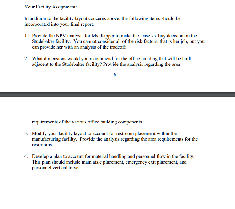
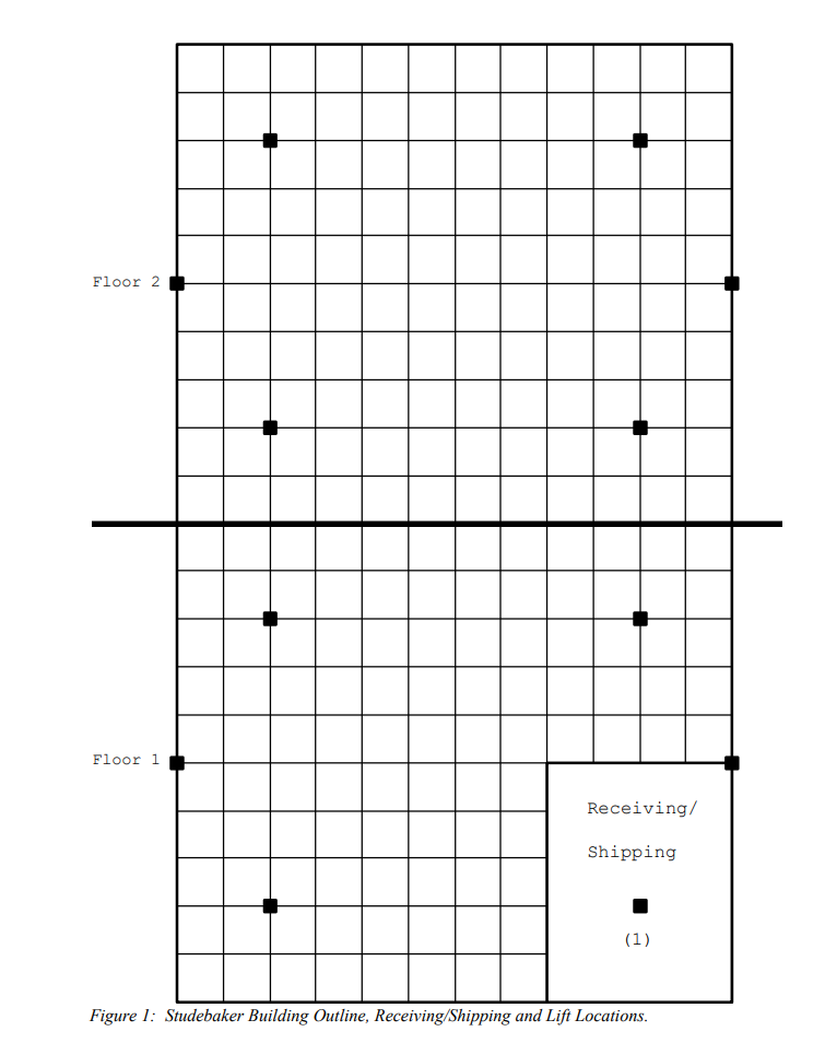
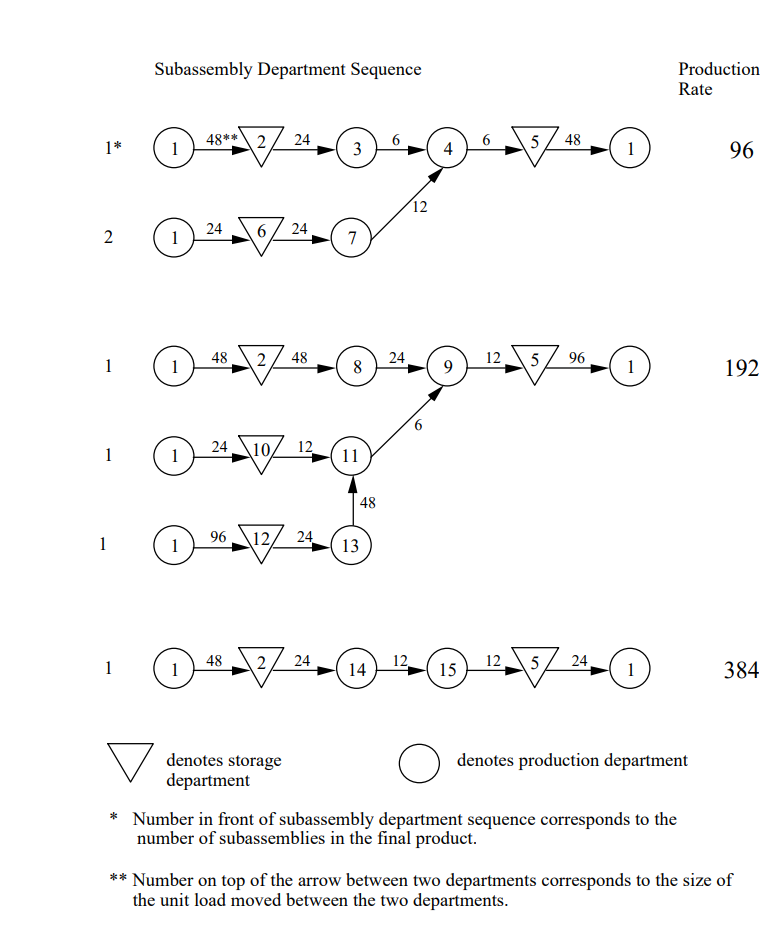
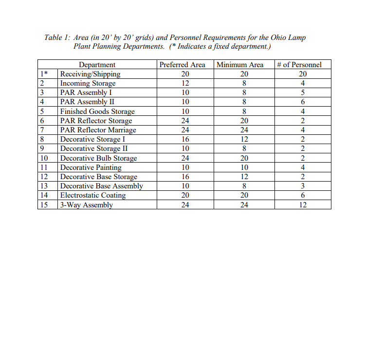
Background: Common Conduit (CC) is one of the three largest incandescent lamp' manufacturers in the world, with manufacturing plants worldwide, but concentrated in the United States. CC manufacturers many different incandescent lamp varieties (at last count 45). Their plant in Warren, Ohio produces 13 of the 45 different lamp varieties. In general, each lamp includes a glass bulb, a metal base, and in between, the filament, some support wires, a support tube and a glass flange. These 13 lamp varieties can be grouped into 3 product families (3-way light bulbs, decorative light bulbs, and parabolic aluminized reflector lamps). The three-way light bulbs have the highest demand. Current production rates of 384 bulbs per hour cannot meet the current demand. The decorative light bulbs (e.g., colored bulbs, "Gro and Sho," etc.) are usually painted and their production rate is set at 192 bulbs per hour. Finally, the parabolic aluminized reflector (PAR) lamps, which are commonly referred to as spotlights, are not bulbs, but rather an open-topped reflector with a piece of round flat glass glued onto the top. The hourly production rate is set at 96 for the PARs. CC's Warren plant (the Warren Lamp Plant, or WLP for short) currently occupies an older three-story facility. Since the lease will expire soon and the company is on a growth path, a new facility plan must be composed. Expanding the current facility would be costly due to its location, and CC isn't sure that the current owner would be willing to do so. The 1 Incandescent lamps are commonly known as light bulbs. staff at WLP has entered into discussions concerning a two-story industrial facility located nearby, which was recently owned by Studebaker Electric. The facility is currently vacant and all the results obtained from an initial evaluation of the condition of the building indicate that it would be a suitable facility for the WLP. Moving into this 96,000 ft facility, and increasing production from 8 hours to 12 hours per day with a part-time student line will allow WLP to meet increasing demand. The building outline for the Studebaker facility is shown in Figure 1, where a 20' x 20' grid size has been used. Some modifications will have to be made to the facility so that it is useable to CC, but the current owner has indicated a willingness to work with CC on this matter if they decide to lease it. In the event that CC purchases the building, CC would be responsible for all expenses incurred in modification. One of the other positive aspects concerning the Studebaker facility is that there is sufficient room in the front of the facility (opposite receiving and shipping) to add an adjacent office building for clerical offices, restrooms, a cafeteria and meeting room, and a nursing station. There is not enough room in the plant for these departments and CC would like to keep them separated from the manufacturing departments as much as possible. More data are provided later on the Studebaker building lease vs. buy decision. The Bulb Production System: The three bulb product families, i.e., the 3-Ways, Decs, and PARs, are similar in components and share a few of the same storage departments. However, different processing departments are used in the production of the bulbs. Figure 2 illustrates the flow for each of the product families, with the PARs illustrated first, the Decs illustrated second, and the 3-Ways illustrated last. Note that each number outlined by a circle or a triangle in Figure 2 denotes a production department or a storage department, respectively. Figure 2 illustrates that the PARs have one main assembly routing and one sub-assembly routing (that corresponds to the glass top and metal reflector). Figure 2 also illustrates that the Decs have one main assembly routing and two sub-assembly routing. Finally, Figure 2 illustrates that the 3-Ways have one main assembly routing. The asterisks in Figure 2 explain the function of the numbers in front of the production routings (sub- assembly multipliers) and the numbers on top of the arrows between the departments (material handling unit load sizes). The planning departments and the data associated for each department are shown in Table 1. Each department's data includes both a preferred area and a minimum area, which provides some flexibility in determining a layout. Also provided in Table 1 is the number of employees in each planning department. As seen from Table 1, there are a total of 15 planning departments. For now we have ignored personnel requirements (restrooms, cafeteria, breakrooms, offices, etc.). These necessary functions will be addressed in the second stage of the facilities design process when the adjacent office building is designed. Departments 1, 2, and 5 are common to all product families. Departments 3, 4, 6, and 7 are exclusively for PAR production. Departments 8 13 are exclusively for Dec production. Departments 14 and 15 are exclusively for 3-Way production. Note that Department 1, the receiving/shipping department, has been fixed to a particular location due to the current location of docks in the facility. This location is shown in Figure 1. The material handling cost for the daily production of light bulbs is the main criterion used by CC to evaluate the effectiveness of a layout. The horizontal cost to travel one grid (20') is assumed to be $0.10 - except for when the receiving/shipping department is involved where we assume a cost of $0.025 for one grid of horizontal travel due to more efficient material handling methods. In the new facility the distance between the two floors is 18 feet and the vertical cost is $0.50 and $0.125 per 18 feet (the less expensive cost applies to flows involving the receiving/shipping department). Facility Issues: Note that Figure 1 indicates the location of the existing lifts in the facility. We may decide to close some of them later, but for now, we can assume that they are all "open." Studebaker is willing to sell their building or lease it to CC. The annual lease cost is $4.00 per square foot net' and the selling price will probably be approximately $3.5M". In the case of the lease, Studebaker indicated that they would spend up to $150,000 to customize the space to suit CC's needs if CC signs a 10-year lease. Studebaker indicated that the lease would contain a cost of living increase after five years. Ms. Kipper indicated that lease payments are 100% tax-deductible and the interest payments on the mortgage are also tax-deductible. The principal payments on the mortgage are not tax-deductible, but as owner, CC would depreciate the building over 39 years. In either case, annual maintenance costs are predicted to be $50,000. Within CC, Ms. Kipper bases economic decisions on NPV calculations. The WLP plant manager, Fred Meyer, uses a payback period analysis when recommending projects. Since the two methods aren't always consistent, this has been a source of friction between the two. In fact, Mr. Meyer doesn't believe that Ms. Kipper understands other plant issues. In the office building that CC will build adjacent to the Studebaker facility, they will need to provide 1,250 ft for the offices, but the requirements for a cafeteria (which will also be used as a meeting room), the restrooms, and a nurse's station must still be determined. Your Layout Assignment: You are to develop a block layout for CC in the Studebaker facility and assess the economic impact of your recommendation (i.e., what is the NPV of the projected maintenance and material handling costs). To do so, you must first develop a from-to chart. The from-to chart will be used as the main method for representing the material handling flow in the WLP facility. Note that multi-floor facility layout algorithms are available, as discussed in Facilities Planning (Tompkins, et al., 2e, 1996). Practical issues in multi-floor facility layout are also discussed in Bozer, Meller and Erlebacher (Management Science, 1994). 2 Under a net lease the tenant pays a base rent and is responsible for all the operating expenses except, for example, the repair and replacement of the building structure and the roof. 3 At current, capital can be secured for a 30-year mortgage at 8% assuming the standard 20% down payment. 4 Profits of CC are subject to a 40% corporate tax rate. 5 CC's internal after-tax rate of return is 21%. 6 Approximately 12 employees occupy the offices. Your final layout will be generally evaluated on the following points (presented in their order of importance): 1. Hourly material handling cost of your final layout. 2. Department shapes. 3. Overall production flow pattern for the two products. In addition to the from-to chart, your final layout, and the net present value of your final layout material handling costs, also present a detailed report to Ms. Kipper and her engineering staff on the advantages and disadvantages of your layout, and the general methodology that you used to arrive at the final layout that you are recommending. She has provided the following notes for the format of the report. The entire report should be typed single-sided on 8.5" by 11" paper with cover sheet, page numbers, table of contents, references, appendices, and ample margins. Your final layout should be a block layout, drawn either using the blank building outline provided along with this handout or a duplicate layout that you produce on your own. Each department in the layout should be CLEARLY labeled by the department name and number, and the BOUNDARIES for all departments should be CLEARLY shown. Make three additional copies of the final layout. On each copy show the overall flow pattern in color for one of the three product families. You are encouraged (but not required) to show intermediate layouts that you obtain as you progress toward your final layout. Intermediate layouts need not be drawn precisely as long as they are presented clearly. Regardless of the number of intermediate layouts or alternative layouts you generate, you have to select ONLY ONE OF THEM as your final layout and present it as stated above. Graphs or tables that summarize key results should be presented in the main body of the report. All detailed NPV computations and support for your layout methodology should be presented in appropriate appendices. Your Facility Assignment: In addition to the facility layout concerns above, the following items should be incorporated into your final report. 1. Provide the NPV-analysis for Ms. Kipper to make the lease vs. buy decision on the Studebaker facility. You cannot consider all of the risk factors, that is her job, but you can provide her with an analysis of the tradeoff. 2. What dimensions would you recommend for the office building that will be built adjacent to the Studebaker facility? Provide the analysis regarding the area requirements of the various office building components. 3. Modify your facility layout to account for restroom placement within the manufacturing facility. Provide the analysis regarding the area requirements for the restrooms. 4. Develop a plan to account for material handling and personnel flow in the facility. This plan should include main aisle placement, emergency exit placement, and personnel vertical travel. Floor 2 Floor 1 Receiving/ Shipping (1) Figure 1: Studebaker Building Outline, Receiving/Shipping and Lift Locations. Subassembly Department Sequence Production Rate 5481 4 1 04-7--04-04740 96 2 02--01 48 2 / 48 5/ 96 I 04-7--0405-0192 192 48 10*--00140 384 denotes production department denotes storage department * Number in front of subassembly department sequence corresponds to the number of subassemblies in the final product. ** Number on top of the arrow between two departments corresponds to the size of the unit load moved between the two departments. Table 1: Area (in 20' by 20' grids) and Personnel Requirements for the Ohio Lamp Plant Planning Departments. (* Indicates a fixed department.) Preferred Area Minimum Areal # of Personnel 1* 20 20 4 7 8 Department Receiving/Shipping Incoming Storage PAR Assembly I PAR Assembly II Finished Goods Storage PAR Reflector Storage PAR Reflector Marriage Decorative Storage I Decorative Storage II Decorative Bulb Storage Decorative Painting Decorative Base Storage Decorative Base Assembly Electrostatic Coating 3-Way Assembly 9 10 11 12 13 14 15 Background: Common Conduit (CC) is one of the three largest incandescent lamp' manufacturers in the world, with manufacturing plants worldwide, but concentrated in the United States. CC manufacturers many different incandescent lamp varieties (at last count 45). Their plant in Warren, Ohio produces 13 of the 45 different lamp varieties. In general, each lamp includes a glass bulb, a metal base, and in between, the filament, some support wires, a support tube and a glass flange. These 13 lamp varieties can be grouped into 3 product families (3-way light bulbs, decorative light bulbs, and parabolic aluminized reflector lamps). The three-way light bulbs have the highest demand. Current production rates of 384 bulbs per hour cannot meet the current demand. The decorative light bulbs (e.g., colored bulbs, "Gro and Sho," etc.) are usually painted and their production rate is set at 192 bulbs per hour. Finally, the parabolic aluminized reflector (PAR) lamps, which are commonly referred to as spotlights, are not bulbs, but rather an open-topped reflector with a piece of round flat glass glued onto the top. The hourly production rate is set at 96 for the PARs. CC's Warren plant (the Warren Lamp Plant, or WLP for short) currently occupies an older three-story facility. Since the lease will expire soon and the company is on a growth path, a new facility plan must be composed. Expanding the current facility would be costly due to its location, and CC isn't sure that the current owner would be willing to do so. The 1 Incandescent lamps are commonly known as light bulbs. staff at WLP has entered into discussions concerning a two-story industrial facility located nearby, which was recently owned by Studebaker Electric. The facility is currently vacant and all the results obtained from an initial evaluation of the condition of the building indicate that it would be a suitable facility for the WLP. Moving into this 96,000 ft facility, and increasing production from 8 hours to 12 hours per day with a part-time student line will allow WLP to meet increasing demand. The building outline for the Studebaker facility is shown in Figure 1, where a 20' x 20' grid size has been used. Some modifications will have to be made to the facility so that it is useable to CC, but the current owner has indicated a willingness to work with CC on this matter if they decide to lease it. In the event that CC purchases the building, CC would be responsible for all expenses incurred in modification. One of the other positive aspects concerning the Studebaker facility is that there is sufficient room in the front of the facility (opposite receiving and shipping) to add an adjacent office building for clerical offices, restrooms, a cafeteria and meeting room, and a nursing station. There is not enough room in the plant for these departments and CC would like to keep them separated from the manufacturing departments as much as possible. More data are provided later on the Studebaker building lease vs. buy decision. The Bulb Production System: The three bulb product families, i.e., the 3-Ways, Decs, and PARs, are similar in components and share a few of the same storage departments. However, different processing departments are used in the production of the bulbs. Figure 2 illustrates the flow for each of the product families, with the PARs illustrated first, the Decs illustrated second, and the 3-Ways illustrated last. Note that each number outlined by a circle or a triangle in Figure 2 denotes a production department or a storage department, respectively. Figure 2 illustrates that the PARs have one main assembly routing and one sub-assembly routing (that corresponds to the glass top and metal reflector). Figure 2 also illustrates that the Decs have one main assembly routing and two sub-assembly routing. Finally, Figure 2 illustrates that the 3-Ways have one main assembly routing. The asterisks in Figure 2 explain the function of the numbers in front of the production routings (sub- assembly multipliers) and the numbers on top of the arrows between the departments (material handling unit load sizes). The planning departments and the data associated for each department are shown in Table 1. Each department's data includes both a preferred area and a minimum area, which provides some flexibility in determining a layout. Also provided in Table 1 is the number of employees in each planning department. As seen from Table 1, there are a total of 15 planning departments. For now we have ignored personnel requirements (restrooms, cafeteria, breakrooms, offices, etc.). These necessary functions will be addressed in the second stage of the facilities design process when the adjacent office building is designed. Departments 1, 2, and 5 are common to all product families. Departments 3, 4, 6, and 7 are exclusively for PAR production. Departments 8 13 are exclusively for Dec production. Departments 14 and 15 are exclusively for 3-Way production. Note that Department 1, the receiving/shipping department, has been fixed to a particular location due to the current location of docks in the facility. This location is shown in Figure 1. The material handling cost for the daily production of light bulbs is the main criterion used by CC to evaluate the effectiveness of a layout. The horizontal cost to travel one grid (20') is assumed to be $0.10 - except for when the receiving/shipping department is involved where we assume a cost of $0.025 for one grid of horizontal travel due to more efficient material handling methods. In the new facility the distance between the two floors is 18 feet and the vertical cost is $0.50 and $0.125 per 18 feet (the less expensive cost applies to flows involving the receiving/shipping department). Facility Issues: Note that Figure 1 indicates the location of the existing lifts in the facility. We may decide to close some of them later, but for now, we can assume that they are all "open." Studebaker is willing to sell their building or lease it to CC. The annual lease cost is $4.00 per square foot net' and the selling price will probably be approximately $3.5M". In the case of the lease, Studebaker indicated that they would spend up to $150,000 to customize the space to suit CC's needs if CC signs a 10-year lease. Studebaker indicated that the lease would contain a cost of living increase after five years. Ms. Kipper indicated that lease payments are 100% tax-deductible and the interest payments on the mortgage are also tax-deductible. The principal payments on the mortgage are not tax-deductible, but as owner, CC would depreciate the building over 39 years. In either case, annual maintenance costs are predicted to be $50,000. Within CC, Ms. Kipper bases economic decisions on NPV calculations. The WLP plant manager, Fred Meyer, uses a payback period analysis when recommending projects. Since the two methods aren't always consistent, this has been a source of friction between the two. In fact, Mr. Meyer doesn't believe that Ms. Kipper understands other plant issues. In the office building that CC will build adjacent to the Studebaker facility, they will need to provide 1,250 ft for the offices, but the requirements for a cafeteria (which will also be used as a meeting room), the restrooms, and a nurse's station must still be determined. Your Layout Assignment: You are to develop a block layout for CC in the Studebaker facility and assess the economic impact of your recommendation (i.e., what is the NPV of the projected maintenance and material handling costs). To do so, you must first develop a from-to chart. The from-to chart will be used as the main method for representing the material handling flow in the WLP facility. Note that multi-floor facility layout algorithms are available, as discussed in Facilities Planning (Tompkins, et al., 2e, 1996). Practical issues in multi-floor facility layout are also discussed in Bozer, Meller and Erlebacher (Management Science, 1994). 2 Under a net lease the tenant pays a base rent and is responsible for all the operating expenses except, for example, the repair and replacement of the building structure and the roof. 3 At current, capital can be secured for a 30-year mortgage at 8% assuming the standard 20% down payment. 4 Profits of CC are subject to a 40% corporate tax rate. 5 CC's internal after-tax rate of return is 21%. 6 Approximately 12 employees occupy the offices. Your final layout will be generally evaluated on the following points (presented in their order of importance): 1. Hourly material handling cost of your final layout. 2. Department shapes. 3. Overall production flow pattern for the two products. In addition to the from-to chart, your final layout, and the net present value of your final layout material handling costs, also present a detailed report to Ms. Kipper and her engineering staff on the advantages and disadvantages of your layout, and the general methodology that you used to arrive at the final layout that you are recommending. She has provided the following notes for the format of the report. The entire report should be typed single-sided on 8.5" by 11" paper with cover sheet, page numbers, table of contents, references, appendices, and ample margins. Your final layout should be a block layout, drawn either using the blank building outline provided along with this handout or a duplicate layout that you produce on your own. Each department in the layout should be CLEARLY labeled by the department name and number, and the BOUNDARIES for all departments should be CLEARLY shown. Make three additional copies of the final layout. On each copy show the overall flow pattern in color for one of the three product families. You are encouraged (but not required) to show intermediate layouts that you obtain as you progress toward your final layout. Intermediate layouts need not be drawn precisely as long as they are presented clearly. Regardless of the number of intermediate layouts or alternative layouts you generate, you have to select ONLY ONE OF THEM as your final layout and present it as stated above. Graphs or tables that summarize key results should be presented in the main body of the report. All detailed NPV computations and support for your layout methodology should be presented in appropriate appendices. Your Facility Assignment: In addition to the facility layout concerns above, the following items should be incorporated into your final report. 1. Provide the NPV-analysis for Ms. Kipper to make the lease vs. buy decision on the Studebaker facility. You cannot consider all of the risk factors, that is her job, but you can provide her with an analysis of the tradeoff. 2. What dimensions would you recommend for the office building that will be built adjacent to the Studebaker facility? Provide the analysis regarding the area requirements of the various office building components. 3. Modify your facility layout to account for restroom placement within the manufacturing facility. Provide the analysis regarding the area requirements for the restrooms. 4. Develop a plan to account for material handling and personnel flow in the facility. This plan should include main aisle placement, emergency exit placement, and personnel vertical travel. Floor 2 Floor 1 Receiving/ Shipping (1) Figure 1: Studebaker Building Outline, Receiving/Shipping and Lift Locations. Subassembly Department Sequence Production Rate 5481 4 1 04-7--04-04740 96 2 02--01 48 2 / 48 5/ 96 I 04-7--0405-0192 192 48 10*--00140 384 denotes production department denotes storage department * Number in front of subassembly department sequence corresponds to the number of subassemblies in the final product. ** Number on top of the arrow between two departments corresponds to the size of the unit load moved between the two departments. Table 1: Area (in 20' by 20' grids) and Personnel Requirements for the Ohio Lamp Plant Planning Departments. (* Indicates a fixed department.) Preferred Area Minimum Areal # of Personnel 1* 20 20 4 7 8 Department Receiving/Shipping Incoming Storage PAR Assembly I PAR Assembly II Finished Goods Storage PAR Reflector Storage PAR Reflector Marriage Decorative Storage I Decorative Storage II Decorative Bulb Storage Decorative Painting Decorative Base Storage Decorative Base Assembly Electrostatic Coating 3-Way Assembly 9 10 11 12 13 14 15
Step by Step Solution
There are 3 Steps involved in it

Get step-by-step solutions from verified subject matter experts


