Power Electronics Assignment


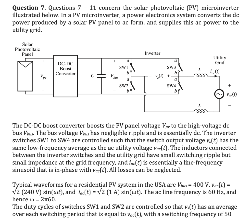
Question 7. Questions 7 - 11 concern the solar photovoltaic (PV) microinverter illustrated below. In a PV microinverter, a power electronics system converts the dc power produced by a solar PV panel to ac form, and supplies this ac power to the utility grid. Solar Photovoltaic Panel Inverter Utility + + a Grid DC-DC Boost Converter SW1 bi L 000 bus a SW3 b9 V. (t) + a SW4 be SW2 be Vac(t) L mo The DC-DC boost converter boosts the PV panel voltage Vpy to the high-voltage dc bus Vbus. The bus voltage Vbus has negligible ripple and is essentially dc. The inverter switches SW1 to SW4 are controlled such that the switch output voltage vs(t) has the same low-frequency average as the ac utility voltage Vac(t). The inductors connected between the inverter switches and the utility grid have small switching ripple but small impedance at the grid frequency, and iac(t) is essentially a line-frequency sinusoid that is in-phase with Vac(t). All losses can be neglected. Typical waveforms for a residential PV system in the USA are Vbus = 400 V, vac(t) = V2 (240 V) sin(wt), and iac(t) = V2 (1 A) sin(wt). The ac line frequency is 60 Hz, and hence w = 2160. The duty cycles of switches SW1 and SW2 are controlled so that vs(t) has an average over each switching period that is equal to Vac(t), with a switching frequency of 50 kHz. Switches SW3 and SW4 are switched at the ac line frequency of 60 Hz: SW3 is on when Vac(t) > 0, and SW4 is on when Vac(t) 0. Your expression should be written in terms of the following variable names: For Vm, enter VM For w, enter w For t, entert For Vbus, enter Vbus You can enter sin x as sin(x) . Question 12. The switching ripple Ai in the current iac(t) varies over the ac utility line cycle. Calculate the maximum value of the ripple Ai (in amps), for the following element values: AC utility voltage is 240 Vrms DC bus voltage is 400 V dc Switching frequency of SW1 and SW2 is 70 kHz Inductance L = 1.5 mH Question 7. Questions 7 - 11 concern the solar photovoltaic (PV) microinverter illustrated below. In a PV microinverter, a power electronics system converts the dc power produced by a solar PV panel to ac form, and supplies this ac power to the utility grid. Solar Photovoltaic Panel Inverter Utility + + a Grid DC-DC Boost Converter SW1 bi L 000 bus a SW3 b9 V. (t) + a SW4 be SW2 be Vac(t) L mo The DC-DC boost converter boosts the PV panel voltage Vpy to the high-voltage dc bus Vbus. The bus voltage Vbus has negligible ripple and is essentially dc. The inverter switches SW1 to SW4 are controlled such that the switch output voltage vs(t) has the same low-frequency average as the ac utility voltage Vac(t). The inductors connected between the inverter switches and the utility grid have small switching ripple but small impedance at the grid frequency, and iac(t) is essentially a line-frequency sinusoid that is in-phase with Vac(t). All losses can be neglected. Typical waveforms for a residential PV system in the USA are Vbus = 400 V, vac(t) = V2 (240 V) sin(wt), and iac(t) = V2 (1 A) sin(wt). The ac line frequency is 60 Hz, and hence w = 2160. The duty cycles of switches SW1 and SW2 are controlled so that vs(t) has an average over each switching period that is equal to Vac(t), with a switching frequency of 50 kHz. Switches SW3 and SW4 are switched at the ac line frequency of 60 Hz: SW3 is on when Vac(t) > 0, and SW4 is on when Vac(t) 0. Your expression should be written in terms of the following variable names: For Vm, enter VM For w, enter w For t, entert For Vbus, enter Vbus You can enter sin x as sin(x) . Question 12. The switching ripple Ai in the current iac(t) varies over the ac utility line cycle. Calculate the maximum value of the ripple Ai (in amps), for the following element values: AC utility voltage is 240 Vrms DC bus voltage is 400 V dc Switching frequency of SW1 and SW2 is 70 kHz Inductance L = 1.5 mH


