Question
PROBLEM 3: A local school is planning to organize a Science Quiz for its students. After the preliminary selection rounds, 5 teams will make it
PROBLEM 3:
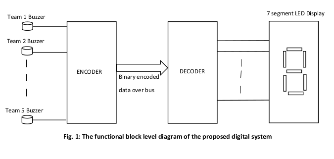
A local school is planning to organize a Science Quiz for its students. After the preliminary selection rounds, 5 teams will make it into the final level. The final round is an on-stage event where all the teams will be provided with buzzers. Upon being provided with a question, the team to first press the buzzer will be allowed to answer the question. The organizers have decided to use a display showing the team number who pressed the buzzer for more visibility to the audience. For example, if team 2 pressed the buzzer, the display will show 2. You need to design the buzzer system for the quiz. You decided to use an encoder, a decoder and 7-segment LED display for this purpose. The functional diagram of the system is given below


I only need 1, 3, and 4.
7 segment LED Display Team 1 Buzzer u Team 2 Buzzer ENCODER DECODER Binary encoded data over bus Team 5 Buzzer Fig. 1: The functional block level diagram of the proposed digital system Activities to do- 1. Identify the following design parameters - a. Number of the bits/wires required in the data bus. b. Size of the encoder and decoder. 2. Read one of the 7 segment LED display data sheet, try to understand how to use it. 3. Design the encoder and decoder blocks with basic logic gates then incorporate the same into a complete digital system on Logisim. 4. Did you encounter any don't care condition? What did you substitute for such don't cares? How does your choice affect the result? 7 segment LED Display Team 1 Buzzer u Team 2 Buzzer ENCODER DECODER Binary encoded data over bus Team 5 Buzzer Fig. 1: The functional block level diagram of the proposed digital system Activities to do- 1. Identify the following design parameters - a. Number of the bits/wires required in the data bus. b. Size of the encoder and decoder. 2. Read one of the 7 segment LED display data sheet, try to understand how to use it. 3. Design the encoder and decoder blocks with basic logic gates then incorporate the same into a complete digital system on Logisim. 4. Did you encounter any don't care condition? What did you substitute for such don't cares? How does your choice affect the resultStep by Step Solution
There are 3 Steps involved in it
Step: 1

Get Instant Access to Expert-Tailored Solutions
See step-by-step solutions with expert insights and AI powered tools for academic success
Step: 2

Step: 3

Ace Your Homework with AI
Get the answers you need in no time with our AI-driven, step-by-step assistance
Get Started


