Answered step by step
Verified Expert Solution
Question
1 Approved Answer
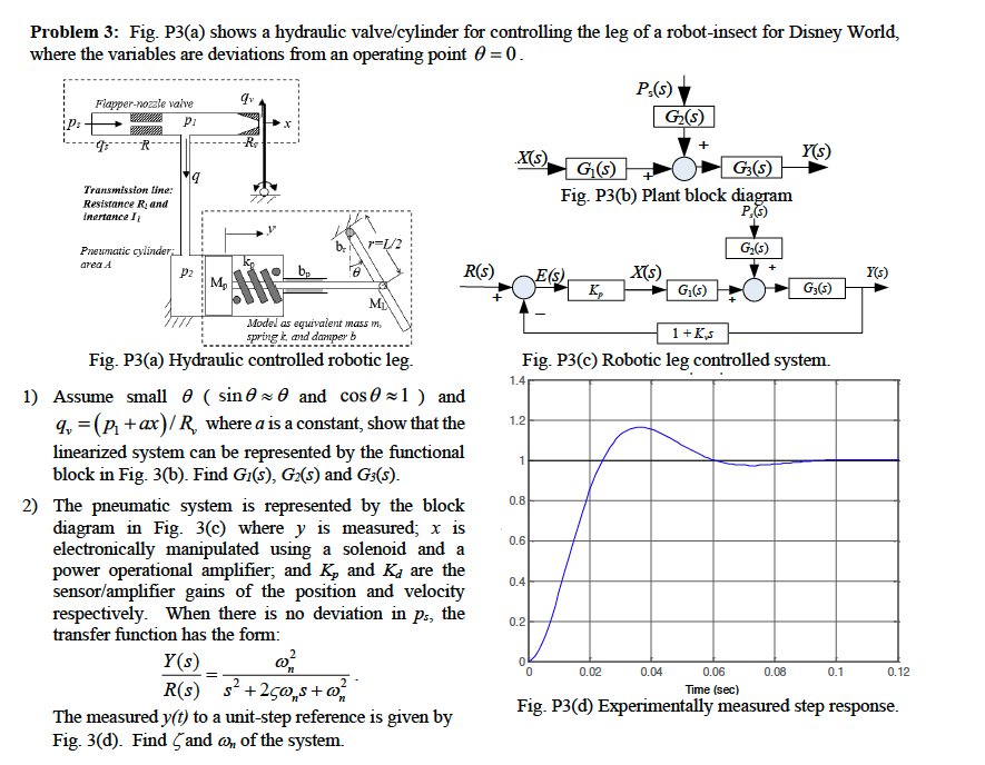
Problem 3: Fig. P3(a) shows a hydraulic valve/cylinder for controlling the leg of a robot-insect for Disney World, where the variables are deviations from

Problem 3: Fig. P3(a) shows a hydraulic valve/cylinder for controlling the leg of a robot-insect for Disney World, where the variables are deviations from an operating point 0 = 0. P(s) Flapper-nozzle valve qv G(s) p1 x -Re + .X(s) Y(s) G(s) G3(S) 19 Transmission line: Fig. P3(b) Plant block diagram Resistance R, and P(s) inertance I \=1/2 G(5) Pneumatic cylinder area A Pz k M R(s) E(s) X(s) Y(s) K G(5) G3(5) M Model as equivalent mass m spring k, and damper b Fig. P3(a) Hydraulic controlled robotic leg. 1) Assume small (sin and cos1) and 9, (P+ax)/R, where a is a constant, show that the linearized system can be represented by the functional block in Fig. 3(b). Find G1(s), G(s) and G3(5). 2) The pneumatic system is represented by the block diagram in Fig. 3(c) where y is measured; x is electronically manipulated using a solenoid and a power operational amplifier; and K, and Ka are the sensor/amplifier gains of the position and velocity respectively. When there is no deviation in ps, the transfer function has the form: Y(s) R(s) s +25ws+w The measured y(t) to a unit-step reference is given by Fig. 3(d). Find and w, of the system. 1.4 1.2 1 0.8 0.6 0.4 0.2 1+Ks Fig. P3(c) Robotic leg controlled system. 0 0.02 0.04 0.06 0.08 0.1 0.12 Time (sec) Fig. P3(d) Experimentally measured step response.
Step by Step Solution
There are 3 Steps involved in it
Step: 1

Get Instant Access to Expert-Tailored Solutions
See step-by-step solutions with expert insights and AI powered tools for academic success
Step: 2

Step: 3

Ace Your Homework with AI
Get the answers you need in no time with our AI-driven, step-by-step assistance
Get Started


