Answered step by step
Verified Expert Solution
Question
1 Approved Answer
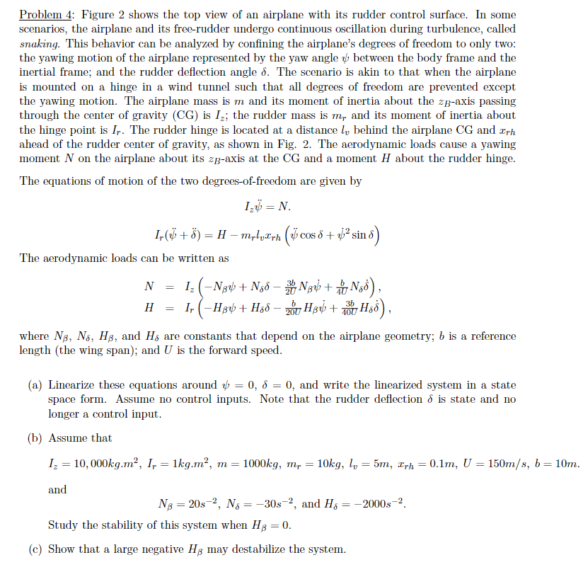
Problem 4: Figure 2 shows the top view of an airplane with its rudder control surface. In some scenarios, the airplane and its free-rudder


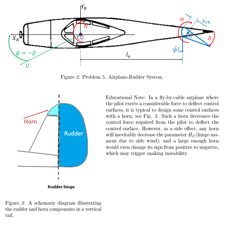
Problem 4: Figure 2 shows the top view of an airplane with its rudder control surface. In some scenarios, the airplane and its free-rudder undergo continuous oscillation during turbulence, called snaking. This behavior can be analyzed by confining the airplane's degrees of freedom to only two: the yawing motion of the airplane represented by the yaw angle between the body frame and the inertial frame; and the rudder deflection angle 8. The scenario is akin to that when the airplane is mounted on a hinge in a wind tunnel such that all degrees of freedom are prevented except the yawing motion. The airplane mass is m and its moment of inertia about the z-axis passing through the center of gravity (CG) is I; the rudder mass is m, and its moment of inertia about the hinge point is Ir. The rudder hinge is located at a distance, behind the airplane CG and arh ahead of the rudder center of gravity, as shown in Fig. 2. The aerodynamic loads cause a yawing moment N on the airplane about its z-axis at the CG and a moment H about the rudder hinge. The equations of motion of the two degrees-of-freedom are given by Iz = N. Ir(+) = H mrlyrh (cos + sin 8) The aerodynamic loads can be written as N == Iz (3 + Ng N + ), H&S), HI-H+ H88 - H+ H$8 - 200 H3 + = where NB, Ns, HB, and Hs are constants that depend on the airplane geometry; b is a reference length (the wing span); and U is the forward speed. (a) Linearize these equations around = 0, 8 = 0, and write the linearized system in a state space form. Assume no control inputs. Note that the rudder deflection & is state and no longer a control input. (b) Assume that = Iz 10,000kg.m, I, = 1kg.m, m = 1000kg, mr = 10kg, l5m, xrh = == = 0.1m, U 150m/s, b = 10m. and NB = 20s-2, Ns = -30s-2, and H = -2000s-2. Study the stability of this system when HB = 0. (c) Show that a large negative Hg may destabilize the system. XB U Horn W Figure 2: Problem 5. Airplane-Rudder System. H xrh Rudder Educational Note: In a fly-by-cable airplane where the pilot exerts a considerable force to deflect control surfaces, it is typical to design some control surfaces with a horn; see Fig. 3. Such a horn decreases the control force required from the pilot to deflect the control surface. However, as a side effect, any horn will inevitably decrease the parameter HB (hinge mo- ment due to side wind); and a large enough horn would even change its sign from positive to negative, which may trigger snaking instability. Rudder hinge Figure 3: A schematic diagram illustrating the rudder and horn components in a vertical tail.
Step by Step Solution
There are 3 Steps involved in it
Step: 1

Get Instant Access to Expert-Tailored Solutions
See step-by-step solutions with expert insights and AI powered tools for academic success
Step: 2

Step: 3

Ace Your Homework with AI
Get the answers you need in no time with our AI-driven, step-by-step assistance
Get Started


