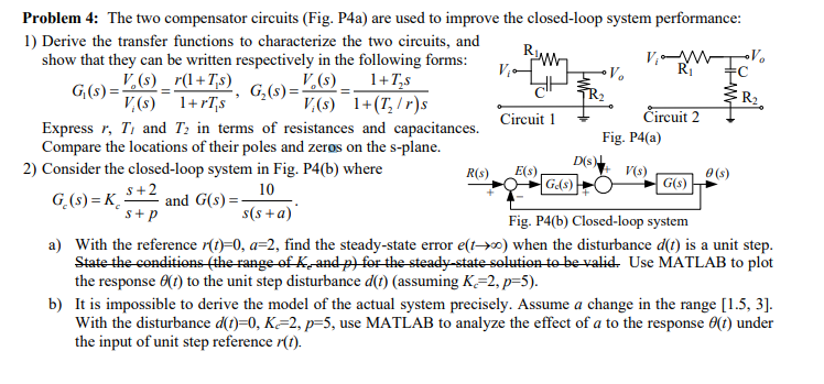
Problem 4: The two compensator circuits (Fig. P4a) are used to improve the closed-loop system performance: 1) Derive the transfer functions to characterize the

Problem 4: The two compensator circuits (Fig. P4a) are used to improve the closed-loop system performance: 1) Derive the transfer functions to characterize the two circuits, and show that they can be written respectively in the following forms: G(s) = (s)_r(1+T,s) 1+TS V,(s) 1+rTs V(s) 1+(T/r)s 5 G(s)=(s) Runy d Circuit 1 R(s) V0 Express r, T and T in terms of resistances and capacitances. Compare the locations of their poles and zeros on the s-plane. 2) Consider the closed-loop system in Fig. P4(b) where 10 Ge(s) G(s)=K_S+2 and G(s)=- s+p s(s+a) Fig. P4(b) Closed-loop system a) With the reference r(t)=0, a=2, find the steady-state error e(tx) when the disturbance d(t) is a unit step. State the conditions (the range of K, and p) for the steady-state solution to be valid. Use MATLAB to plot the response (t) to the unit step disturbance d(t) (assuming K-2, p=5). E(s) Circuit 2 D(s) Fig. P4(a) V(s) G(s) 0 (s) b) It is impossible to derive the model of the actual system precisely. Assume a change in the range [1.5, 3]. With the disturbance d(t)=0, K-2, p=5, use MATLAB to analyze the effect of a to the response 8(t) under the input of unit step reference r(t).
Step by Step Solution
There are 3 Steps involved in it
Step: 1

See step-by-step solutions with expert insights and AI powered tools for academic success
Step: 2

Step: 3

Ace Your Homework with AI
Get the answers you need in no time with our AI-driven, step-by-step assistance
Get Started


