Answered step by step
Verified Expert Solution
Question
1 Approved Answer
PROBLEM 5 (11 PTS) The following die has a sensor on each side. Whenever a side rests on a surface, the sensor on that
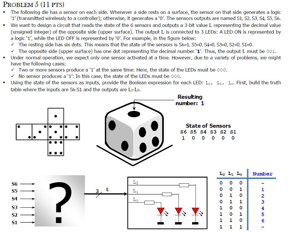
PROBLEM 5 (11 PTS) " The following die has a sensor on each side. Whenever a side rests on a surface, the sensor on that side generates a logic 1' (transmitted wirelessly to a controller); otherwise, it generates a '0'. The sensors outputs are named S1, S2, S3, S4, S5, S6 " We want to design a circuit that reads the state of the 6 sensors and outputs a 3-bit value L representing the decimal value (unsigned integer) of the opposite side (upper surface). The output L is connected to 3 LEDs: A LED ON is represented by a logic '1', while the LED OFF is represented by 0'. For example, in the figure below: The resting side has six dots. This means that the state of the sensors is S6-1, S5-0, S4-0, S3-0, S2-0, S1=0 The opposite side (upper surface) has one dot representing the decimal number '1'. Thus, the output L must be 001. " Under normal operation, we expect only one sensor activated at a time. However, due to a variety of problems, we might have the following cases Two or more sensors produce a '1' at the same time: Here, the state of the LEDs must be 000. No sensor produces a '1': In this case, the state of the LEDs must be 000. Using the state of the sensors as inputs, provide the Boolean expression for each LED:2, Li, Lo. First, build the truth table where the inputs are S6-S1 and the outputs are L2-Lo Resulting number: 1 State of Sensors S6 S5 S4 S3 S2 S1 1 0 0 0 0 0 L2 L1 L0 Number 1 2 3 1 0 0 4 5
Step by Step Solution
There are 3 Steps involved in it
Step: 1
Get Instant Access to Expert-Tailored Solutions
See step-by-step solutions with expert insights and AI powered tools for academic success
Step: 2
Step: 3
Ace Your Homework with AI
Get the answers you need in no time with our AI-driven, step-by-step assistance
Get Started