Answered step by step
Verified Expert Solution
Question
1 Approved Answer
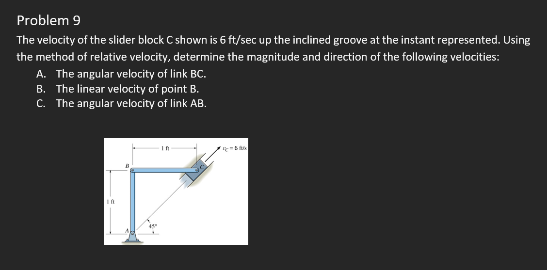
Problem 9 The velocity of the slider block C shown is 6 ft/sec up the inclined groove at the instant represented. Using the method


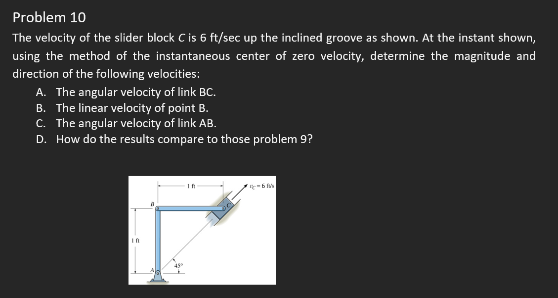
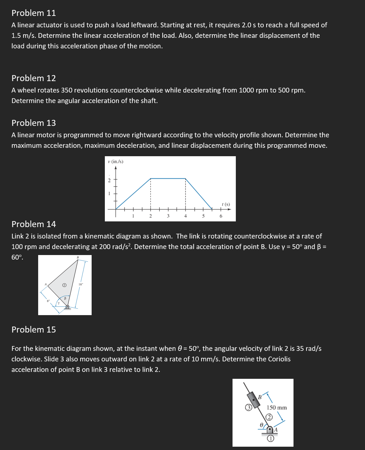
Problem 9 The velocity of the slider block C shown is 6 ft/sec up the inclined groove at the instant represented. Using the method of relative velocity, determine the magnitude and direction of the following velocities: A. The angular velocity of link BC. B. The linear velocity of point B. C. The angular velocity of link AB. 1 ft B 1 ft Uc 6 fus Problem 10 The velocity of the slider block C is 6 ft/sec up the inclined groove as shown. At the instant shown, using the method of the instantaneous center of zero velocity, determine the magnitude and direction of the following velocities: A. The angular velocity of link BC. B. The linear velocity of point B. C. The angular velocity of link AB. D. How do the results compare to those problem 9? 1 ft B 1 ft c=6 fus Problem 11 A linear actuator is used to push a load leftward. Starting at rest, it requires 2.0 s to reach a full speed of 1.5 m/s. Determine the linear acceleration of the load. Also, determine the linear displacement of the load during this acceleration phase of the motion. Problem 12 A wheel rotates 350 revolutions counterclockwise while decelerating from 1000 rpm to 500 rpm. Determine the angular acceleration of the shaft. Problem 13 A linear motor is programmed to move rightward according to the velocity profile shown. Determine the maximum acceleration, maximum deceleration, and linear displacement during this programmed move. v (in./s) Problem 14 2 t(s) 1 2 3 4 5 6 Link 2 is isolated from a kinematic diagram as shown. The link is rotating counterclockwise at a rate of 100 rpm and decelerating at 200 rad/s. Determine the total acceleration of point B. Use y = 50 and = 60. 18" Problem 15 For the kinematic diagram shown, at the instant when 0 = 50, the angular velocity of link 2 is 35 rad/s clockwise. Slide 3 also moves outward on link 2 at a rate of 10 mm/s. Determine the Coriolis acceleration of point B on link 3 relative to link 2. B 150 mm A
Step by Step Solution
There are 3 Steps involved in it
Step: 1

Get Instant Access to Expert-Tailored Solutions
See step-by-step solutions with expert insights and AI powered tools for academic success
Step: 2

Step: 3

Ace Your Homework with AI
Get the answers you need in no time with our AI-driven, step-by-step assistance
Get Started


