Question
Problem: What is the difference (error) in the temperature read by a Type R thermocouple and the actual temperature of the surroundings when the thermocouple
Problem: What is the difference (error) in the temperature read by a Type R thermocouple and the actual temperature of the surroundings when the thermocouple is suspended in 5 m/s, 1000 C air, in an enclosure with wall/surroundings temperature of 25 C?

Thermocouples
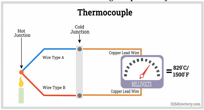
As we saw with the thermoelectric Seebeck effect, when a junction of two dissimilar metals is heated, the difference in EMF between the two materials will produce a measurable potential that can be calibrated and related to the temperature of the junction.
https://www.iqsdirectory.com/articles/thermocouple.html
Even in the simple schematic shown above, there are a few elements worth noting. For the purposes of this problem, we are concerned with Wire A, Wire B, the Hot Junction (also known as the thermocouple bead), and then the copper lead wires and their junction with the two thermocouple wires. The Cold Junction is generally referenced to an ice-water bath at 0 C so the voltage produced by the Hot Junction can be calibrated. See the Omega data sheet (Appendix A) at the end of this problem to see the specific relationship between mV and temperature for a particular thermocouple in this case Type R (one leg is Pt and the other leg is 13% Rh with Pt).
Note that the thermocouple measures the Bead Temperature with the assumption that the Bead is at the temperature of the surroundings. This problem explores the details of this assumption.
Part 1 Identify the physical properties of the thermocouple
We will use a Type R thermocouple (Pt/Pt-13%Rh)
(1a) What is its recommended temperature range in K?
(1b) The Omega website (and the datasheet supplied as Appendix A at the end of this problem) - https://www.omega.com/en-us/colorcodes -- provides the standard error for the Type R thermocouple as the larger of 1.5 C or 0.25%. Above what temperature does the percentage error become larger than 1.5 C? What is the temperature error at 1500K?
As a reasonable estimate, we will assume that the properties of pure Pt apply for the thermocouple (although one of the legs has 13% Rh). Please confirm the following properties are reasonable for Pt at room temperature (25 C) and at high temperature (1000 C) most of these values come from a 1962 (revised 1969) report from the National Bureau of Standards (Thermocouple Materials, F.R. Caldwell, Monograph 40), so feel free to indicate discrepancies with more recent information.
| Properties of Pt | 25 C | 1000 C |
| Density (g/cm3) | 21.45 | 21.23 |
| Specific Heat (kJ/kg-K) | 0.132 | 0.159 |
| Thermal Conductivity (W/m-K) | 69.9 | 89.2 |
| Tensile Strength (MPa) | 143 | 28 |
| Modulus of Elasticity (GPa) | 165 | 129 |
| Total Emissivity* | 0.033 | 0.143 |
*Unfortunately, experimental data on the emissivity of the most common high-temperature thermocouple wires are quite scarce. Compounding this difficulty is the fact that the emissivity of a given metal is strongly dependent on the surface characteristics, including roughness, oxidant layer, and any other coating of the metal, whether intentional or not (C.R. Shading, Correcting thermocouple measurements for radiation loss: a critical review, Proc. 33rd Natl. Heat Transf. Conf., Albuquerque, NM, 1999, pp. 110.).
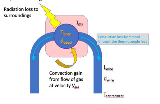
In order to examine the potential impacts of heat loss, we examine just the region near the thermocouple junction, as in the figure below.

The energy balance for this system at steady-state is:

Where subscript b refers to the thermocouple bead. Subscript cat refers to heat generated on the surface of the thermocouple by catalytic reaction effects. We will assume for the moment that the system is in steady state and that catalytic and conduction effects can be neglected. In this case, heat transfer from the gas into the bead by convection balances the heat transfer loss from the bead by radiation.
rad =conv
This equation is to be solved to find the difference between the bead temperature and the gas temperature when the gas temperature is 1000 C and the surroundings temperature is 25 C.
Part 2 Convection heat transfer
In order to calculate the convective heat transfer to the thermocouple bead, assume a flow velocity of 5 m/s, a bead diameter of 1 mm, a surrounding gas of air with a temperature of 1000 C.
Use the following Nusselt number correlation with the Re number based on the bead diameter for the length scale:

With db the bead diameter and kg the gas thermal conductivity at the bead temperature (1000 C). Find the convection heat transfer coefficient for this condition.
Part 3 Time response of the thermocouple bead
Knowing the heat transfer coefficient and the conductivity of the platinum bead (assume a sphere 1 mm in diameter), find the Biot number for the thermocouple and find its time constant.
Part 4 Radiation heat transfer balance the measurement error
By balancing radiation loss with convection heat input to the bead, calculate the temperature difference between the bead temperature and the surrounding gas temperature.
Part 5 Strength of thermocouple to hold its position
Assume that the thermocouple bead is in the 5 m/s flow. Calculate the drag force on the bead and then determine the deflection of the thermocouple wire assuming a Lwire of 1.5 cm and a diameter of the wire dwire = 100 microns. Note that there are two legs to the thermocouple so the drag load is carried on two cantilevered wires.
Conduction loss with the information you have, you could check the conduction loss to see if the assumption of neglecting it is a good one.
Catalytic effects since platinum is an excellent reaction catalyst, it is common to coat Pt thermocouples with a thin layer of silica (glass); you could determine what effects a thin (10 micron) coating of silica does to the heat transfer behavior.
Bead and wire size your conduction loss evaluation shows that conduction loss increases with thickness of the wire, and your time response calculation shows that time response depends on bead size, both suggesting a smaller thermocouple is better. Strength and stability requires larger wire/bead size. How do you go about deciding the optimal thermocouple for the job?
Thermocouple IQSdirectory.com Radiation loss to surroundings \begin{tabular}{|l|} \hline Conductionlossfrombeadthroughthethermocouplelegs \\ \hline \end{tabular} Lwire Convection gain from flow of gas dwire at velocity Vgas Tenvironment mbcp,bdtdT=0=qcond+qconv+qrad+qcat Nu=(0.24+0.56Reb0.45)Nu=kghdb
Step by Step Solution
There are 3 Steps involved in it
Step: 1

Get Instant Access to Expert-Tailored Solutions
See step-by-step solutions with expert insights and AI powered tools for academic success
Step: 2

Step: 3

Ace Your Homework with AI
Get the answers you need in no time with our AI-driven, step-by-step assistance
Get Started


