Answered step by step
Verified Expert Solution
Question
1 Approved Answer
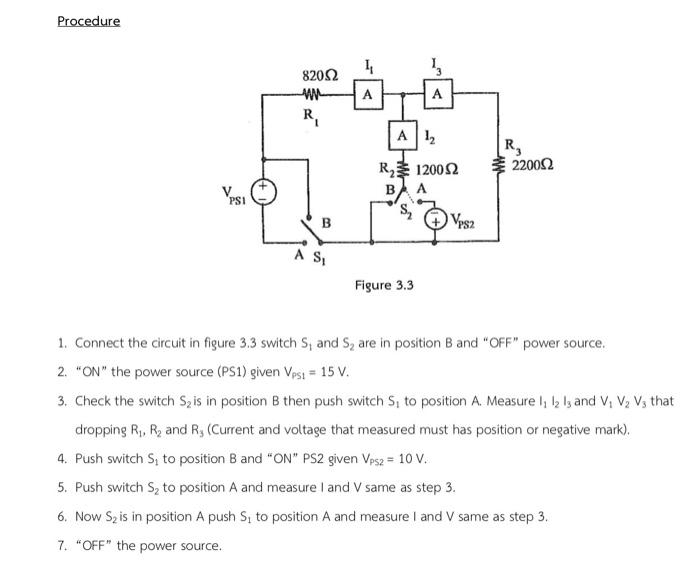
Procedure VPSI 82052 WWW R B A S 4 A Th A 1 R120052 A B S Figure 3.3 VPS2 R 2200 1. Connect


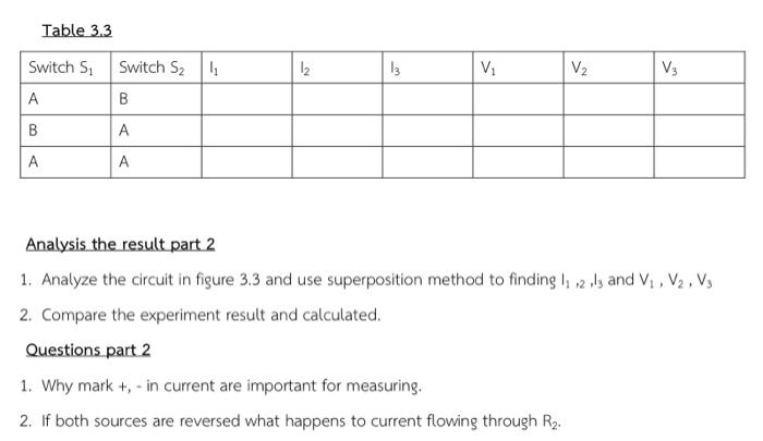
Procedure VPSI 82052 WWW R B A S 4 A Th A 1 R120052 A B S Figure 3.3 VPS2 R 2200 1. Connect the circuit in figure 3.3 switch S, and S are in position B and "OFF" power source. 2. "ON" the power source (PS1) given Vest = 15 V. 3. Check the switch S is in position B then push switch S, to position A. Measure 1 12 13 and V V V3 that dropping R, R and R, (Current and voltage that measured must has position or negative mark). 4. Push switch S, to position B and "ON" PS2 given Vps2 = 10 V. 5. Push switch S to position A and measure I and V same as step 3. 6. Now S is in position A push S, to position A and measure I and V same as step 3. 7. "OFF" the power source. Table 3.3 Switch S A B A Switch S B A A 4 1 13 V V V3 Analysis the result part 2 1. Analyze the circuit in figure 3.3 and use superposition method to finding 1 23 and V, V, V 2. Compare the experiment result and calculated. Questions part 2 1. Why mark +, - in current are important for measuring. 2. If both sources are reversed what happens to current flowing through R.
Step by Step Solution
★★★★★
3.57 Rating (154 Votes )
There are 3 Steps involved in it
Step: 1

Get Instant Access to Expert-Tailored Solutions
See step-by-step solutions with expert insights and AI powered tools for academic success
Step: 2

Step: 3

Ace Your Homework with AI
Get the answers you need in no time with our AI-driven, step-by-step assistance
Get Started


