Answered step by step
Verified Expert Solution
Question
1 Approved Answer
programming skills in assembly language programming. 8051-microcontroller with I/O devices such as, switches, keyboard and LCD display. Please write comment and write if this part


 programming skills in assembly language programming.
8051-microcontroller with I/O devices such as, switches, keyboard and LCD display.
Please write comment and write if this part for Selection 1 or 2 or 3. :)
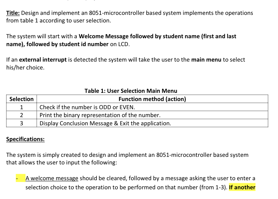
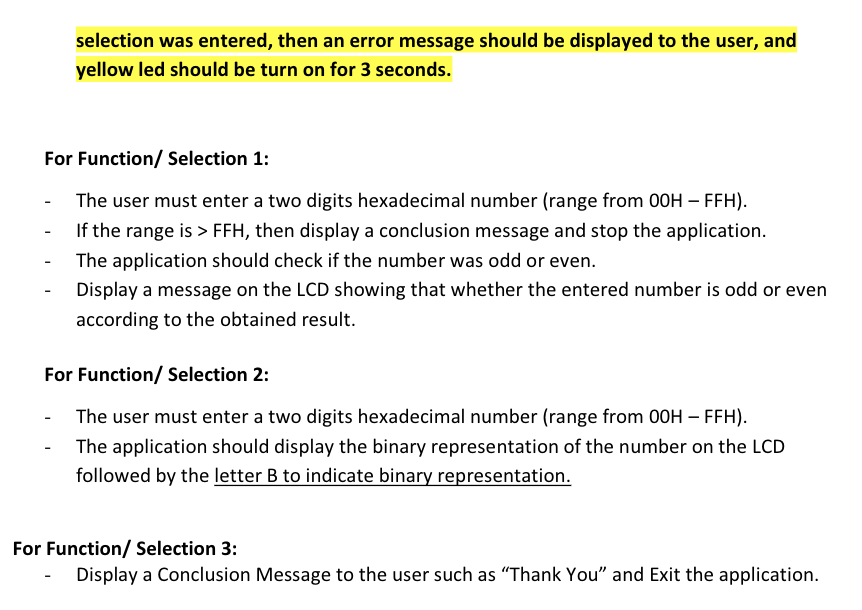
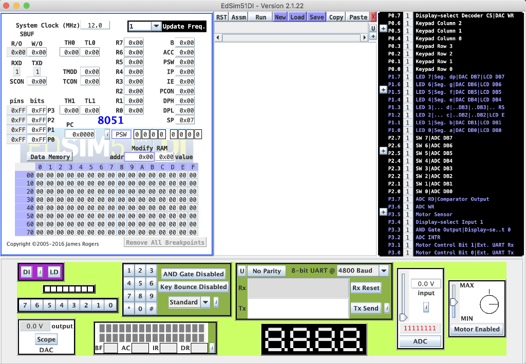
Title: Design and implement an 8051-microcontroller based system implements the operations from table 1 according to user selection. The system will start with a Welcome Message followed by student name (first and last name), followed by student id number on LCD. If an external interrupt is detected the system will take the user to the main menu to select his/her choice. Selection 1 2 3 Table 1: User Selection Main Menu Function method (action) Check if the number is ODD or EVEN. Print the binary representation of the number. Display Conclusion Message & Exit the application. Specifications: The system is simply created to design and implement an 8051-microcontroller based system that allows the user to input the following: A welcome message should be cleared, followed by a message asking the user to enter a selection choice to the operation to be performed on that number (from 1-3). If another selection was entered, then an error message should be displayed to the user, and yellow led should be turn on for 3 seconds. For Function/ Selection 1: The user must enter a two digits hexadecimal number (range from OOH FFH). If the range is > FFH, then display a conclusion message and stop the application. The application should check if the number was odd or even. Display a message on the LCD showing that whether the entered number is odd or even according to the obtained result. For Function/ Selection 2: The user must enter a two digits hexadecimal number (range from OOH FFH). The application should display the binary representation of the number on the LCD followed by the letter B to indicate binary representation. For Function/ Selection 3: Display a Conclusion Message to the user such as "Thank You and Exit the application. Ed Sim51DI - Version 2.1.22 RST Assm Run New Load Save Copy Paste U + System Clock (MHz) 12.0 Update Freq. SBUF R/O W/0 THO TLO R7 Ox00 B 0x00 0x00 0x00 0x00 0x00 R6 Ox00 ACC 0x00 RXD TXD R5 0x00 PSW 0x00 1 1 TMOD 0x00 R4 Ox00 IP Ox00 SCON 0x00 TCON 0x00 R3 Ox00 IE Ox00 R2 0x00 PCON 0x00 pins bits TH1 TL1 R1 Ox00 DPH 0x00 OxFF OxFF P3 0x00 000 RO Ox00 DPL Ox00 OxFF OxFF P2 8051 SP Ox07 PC OxFF OxFFP1 0x0000 PSW 00000000 OxFF OxFF PO Modify RAM Data Memory 0x000x00 value 0 1 2 3 4 5 6 7 8 9 A B C D E F 00 00 00 00 00 00 00 00 00 00 00 00 00 00 00 00 00 10 00 00 00 00 00 00 00 00 00 00 00 00 00 00 00 00 20 00 00 00 00 00 00 00 00 00 00 00 00 00 00 00 00 30 00 00 00 00 00 00 00 00 00 00 00 00 00 00 00 00 40 00 00 00 00 00 00 00 00 00 00 00 00 00 00 00 00 50 00 00 00 00 00 00 00 00 00 00 00 00 00 00 00 00 60 00 00 00 00 00 00 00 00 00 00 00 00 00 00 00 00 70 00 00 00 00 00 00 00 00 00 00 00 00 00 00 00 00 Copyright 2005-2016 James Rogers Remove All Breakpoints P0.7 i Display-select Decoder CS|DAC WR P0.6 i Keypad Column 2 + p0.5 1 Keypad Column 1 PO.4 1 Keypad Column P8.3 1 Keypad Row 3 P0.2 1 Keypad Row 2 P0.1 1 Keypad Row 1 PO. 1 Keypad Row @ P1.7 1 LED 7|Seg. dp|DAC DB7|LCD DB7 P1.6 i LED 6 Seg. g DAC DB6 LCD DB6 P1.5 1 LED 5 Seg. f|DAC DB5 LCD DB5 P1.4 i LED 4 Seg. e DAC DB4 LCD DB4 P1.3 1 LED 31... d..DB3|..DB3.. RS P1.2 1 LED 21... C...DB2..DB2 LCD E P1.1 1 LED 1Seg. DAC DB1LCD DB1 P1.2 1 LED Seg. a|DAC DBO LCD DBO P2.7 i SW 7 ADC DB7 P2.6 1 SW 6 ADC DB6 P2.5 i SW 5ADC DB5 P2.4 1 SW 4|ADC DB4 P2.3 1 SW 3| ADC DB3 P2.2 1 SW 2 | ADC DB2 P2.1 1 SW 1| ADC DB1 P2.0 1 SW | ADC DBO P3.7 1 ADC RD Comparator Output P3.6 1 ADC WR P3.5 1 Motor Sensor P3.4 i Display-select Input 1 P3.3 1 AND Gate Output Display-se..to P3.2 1 ADC INTR P3.1 i Motor Control Bit 1Ext. UART Rx P3.0 i Motor Control Bit Ext. UART TX SIM addr DILD AND Gate Disabled U No Parity 8-bit UART @ 4800 Baud 1 2 3 4 5 6 7 7 8 9 . 0 # Key Bounce Disabled MAX Rx Rx Reset 0.0 V input 7 6 5 4 3 2 1 0 Standard Tx Tx Send MIN 0.0 V output 11111111 E I E Motor Enabled Scope DAC 8:888. ADC BF ACI IR DR Title: Design and implement an 8051-microcontroller based system implements the operations from table 1 according to user selection. The system will start with a Welcome Message followed by student name (first and last name), followed by student id number on LCD. If an external interrupt is detected the system will take the user to the main menu to select his/her choice. Selection 1 2 3 Table 1: User Selection Main Menu Function method (action) Check if the number is ODD or EVEN. Print the binary representation of the number. Display Conclusion Message & Exit the application. Specifications: The system is simply created to design and implement an 8051-microcontroller based system that allows the user to input the following: A welcome message should be cleared, followed by a message asking the user to enter a selection choice to the operation to be performed on that number (from 1-3). If another selection was entered, then an error message should be displayed to the user, and yellow led should be turn on for 3 seconds. For Function/ Selection 1: The user must enter a two digits hexadecimal number (range from OOH FFH). If the range is > FFH, then display a conclusion message and stop the application. The application should check if the number was odd or even. Display a message on the LCD showing that whether the entered number is odd or even according to the obtained result. For Function/ Selection 2: The user must enter a two digits hexadecimal number (range from OOH FFH). The application should display the binary representation of the number on the LCD followed by the letter B to indicate binary representation. For Function/ Selection 3: Display a Conclusion Message to the user such as "Thank You and Exit the application. Ed Sim51DI - Version 2.1.22 RST Assm Run New Load Save Copy Paste U + System Clock (MHz) 12.0 Update Freq. SBUF R/O W/0 THO TLO R7 Ox00 B 0x00 0x00 0x00 0x00 0x00 R6 Ox00 ACC 0x00 RXD TXD R5 0x00 PSW 0x00 1 1 TMOD 0x00 R4 Ox00 IP Ox00 SCON 0x00 TCON 0x00 R3 Ox00 IE Ox00 R2 0x00 PCON 0x00 pins bits TH1 TL1 R1 Ox00 DPH 0x00 OxFF OxFF P3 0x00 000 RO Ox00 DPL Ox00 OxFF OxFF P2 8051 SP Ox07 PC OxFF OxFFP1 0x0000 PSW 00000000 OxFF OxFF PO Modify RAM Data Memory 0x000x00 value 0 1 2 3 4 5 6 7 8 9 A B C D E F 00 00 00 00 00 00 00 00 00 00 00 00 00 00 00 00 00 10 00 00 00 00 00 00 00 00 00 00 00 00 00 00 00 00 20 00 00 00 00 00 00 00 00 00 00 00 00 00 00 00 00 30 00 00 00 00 00 00 00 00 00 00 00 00 00 00 00 00 40 00 00 00 00 00 00 00 00 00 00 00 00 00 00 00 00 50 00 00 00 00 00 00 00 00 00 00 00 00 00 00 00 00 60 00 00 00 00 00 00 00 00 00 00 00 00 00 00 00 00 70 00 00 00 00 00 00 00 00 00 00 00 00 00 00 00 00 Copyright 2005-2016 James Rogers Remove All Breakpoints P0.7 i Display-select Decoder CS|DAC WR P0.6 i Keypad Column 2 + p0.5 1 Keypad Column 1 PO.4 1 Keypad Column P8.3 1 Keypad Row 3 P0.2 1 Keypad Row 2 P0.1 1 Keypad Row 1 PO. 1 Keypad Row @ P1.7 1 LED 7|Seg. dp|DAC DB7|LCD DB7 P1.6 i LED 6 Seg. g DAC DB6 LCD DB6 P1.5 1 LED 5 Seg. f|DAC DB5 LCD DB5 P1.4 i LED 4 Seg. e DAC DB4 LCD DB4 P1.3 1 LED 31... d..DB3|..DB3.. RS P1.2 1 LED 21... C...DB2..DB2 LCD E P1.1 1 LED 1Seg. DAC DB1LCD DB1 P1.2 1 LED Seg. a|DAC DBO LCD DBO P2.7 i SW 7 ADC DB7 P2.6 1 SW 6 ADC DB6 P2.5 i SW 5ADC DB5 P2.4 1 SW 4|ADC DB4 P2.3 1 SW 3| ADC DB3 P2.2 1 SW 2 | ADC DB2 P2.1 1 SW 1| ADC DB1 P2.0 1 SW | ADC DBO P3.7 1 ADC RD Comparator Output P3.6 1 ADC WR P3.5 1 Motor Sensor P3.4 i Display-select Input 1 P3.3 1 AND Gate Output Display-se..to P3.2 1 ADC INTR P3.1 i Motor Control Bit 1Ext. UART Rx P3.0 i Motor Control Bit Ext. UART TX SIM addr DILD AND Gate Disabled U No Parity 8-bit UART @ 4800 Baud 1 2 3 4 5 6 7 7 8 9 . 0 # Key Bounce Disabled MAX Rx Rx Reset 0.0 V input 7 6 5 4 3 2 1 0 Standard Tx Tx Send MIN 0.0 V output 11111111 E I E Motor Enabled Scope DAC 8:888. ADC BF ACI IR DRStep by Step Solution
There are 3 Steps involved in it
Step: 1

Get Instant Access to Expert-Tailored Solutions
See step-by-step solutions with expert insights and AI powered tools for academic success
Step: 2

Step: 3

Ace Your Homework with AI
Get the answers you need in no time with our AI-driven, step-by-step assistance
Get Started


