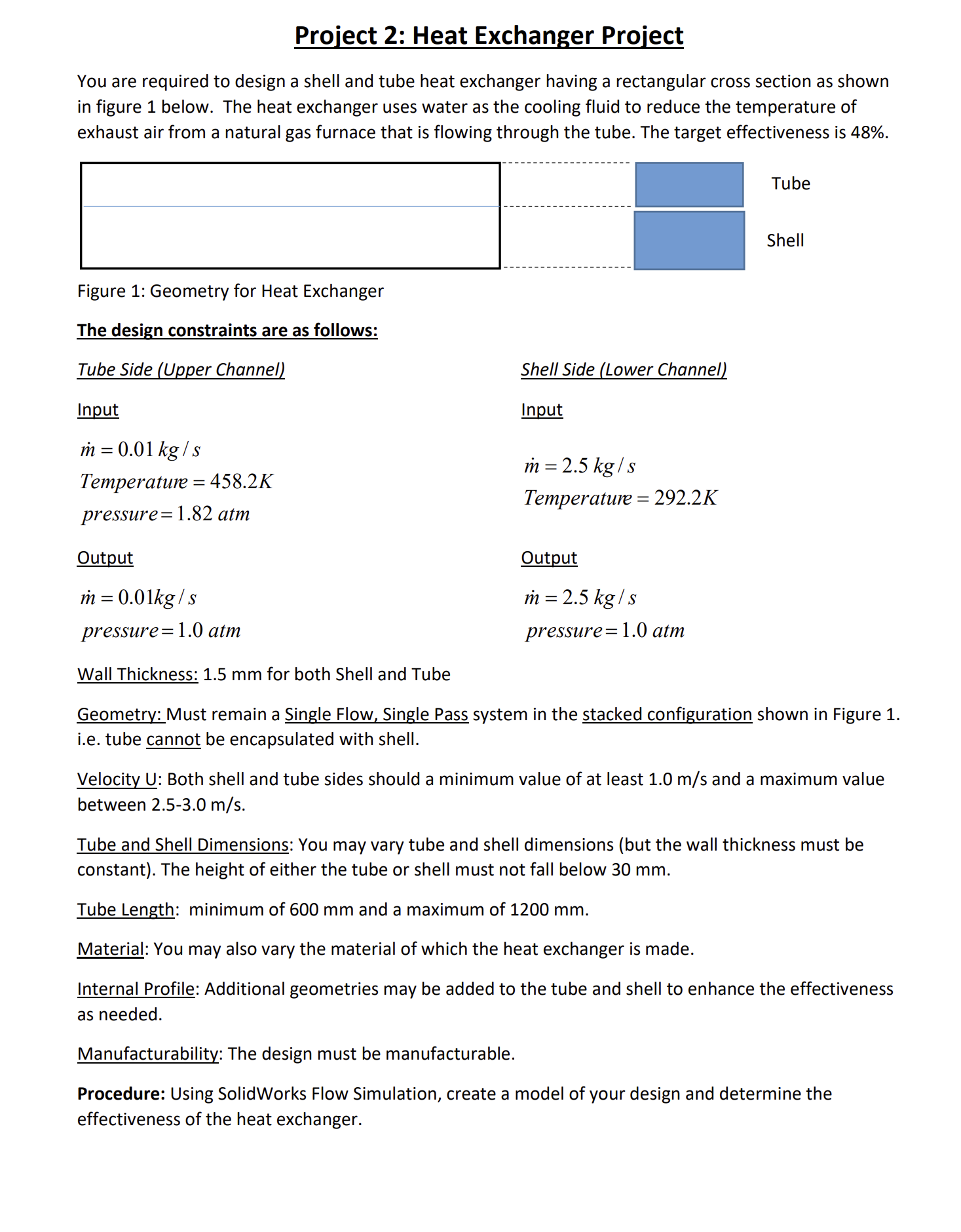
Project 2: Heat Exchanger Project You are required to design a shell and tube heat exchanger having a rectangular cross section as shown in


Project 2: Heat Exchanger Project You are required to design a shell and tube heat exchanger having a rectangular cross section as shown in figure 1 below. The heat exchanger uses water as the cooling fluid to reduce the temperature of exhaust air from a natural gas furnace that is flowing through the tube. The target effectiveness is 48%. Tube Shell Figure 1: Geometry for Heat Exchanger The design constraints are as follows: Tube Side (Upper Channel) Input m = 0.01 kg/s Temperature=458.2K pressure 1.82 atm Output m = 0.01kg/s pressure 1.0 atm Wall Thickness: 1.5 mm for both Shell and Tube Shell Side (Lower Channel) Input m = 2.5 kg/s Temperature = 292.2K Output m = 2.5 kg/s pressure 1.0 atm Geometry: Must remain a Single Flow, Single Pass system in the stacked configuration shown in Figure 1. i.e. tube cannot be encapsulated with shell. Velocity U: Both shell and tube sides should a minimum value of at least 1.0 m/s and a maximum value between 2.5-3.0 m/s. Tube and Shell Dimensions: You may vary tube and shell dimensions (but the wall thickness must be constant). The height of either the tube or shell must not fall below 30 mm. Tube Length: minimum of 600 mm and a maximum of 1200 mm. Material: You may also vary the material of which the heat exchanger is made. Internal Profile: Additional geometries may be added to the tube and shell to enhance the effectiveness as needed. Manufacturability: The design must be manufacturable. Procedure: Using SolidWorks Flow Simulation, create a model of your design and determine the effectiveness of the heat exchanger. Deliverables: PowerPoint presentation, Design Report and Final Part File with Flow Parameter (Check "Assignment" folder for Due Date) Reporting: Your design report should include the following sections: 1. Introduction and Problem Statement (10 points) 2. Model Summary: summary table showing entities such as (but not limited to) number of nodes, number of elements, element type, mesh type, material assignment. Do not print out the entire model data for your simulation. (20 points) 3. Calculations- perform a rough hand calculation for comparison to your simulation results. State ALL assumptions. (15 points) 4. Results: should include plots, tables, graphs etc. to allow for comparison of the simulations that were performed in order for you to arrive at your final answer. It is not required that you print plots (e.g. cut plots) for every simulation. However, you will need to summarize your results graphically or in table form. You should also present the appropriate flow parameters from your simulation to support your final design. (30 points) 5. Discussion and Conclusion: discuss your results relative to what was expected and make appropriate conclusions. Include sources of errors and recommendations for future work.(20 points) 6. Bibliography: list all sources used or referenced in your project. (5 points)
Step by Step Solution
There are 3 Steps involved in it
Step: 1
Solutions Step 1 ImageDescription The image shows a diagram of a shell and tube heat exchanger with a rectangular crosssection The heat exchanger uses ...
See step-by-step solutions with expert insights and AI powered tools for academic success
Step: 2

Step: 3

Ace Your Homework with AI
Get the answers you need in no time with our AI-driven, step-by-step assistance
Get Started


