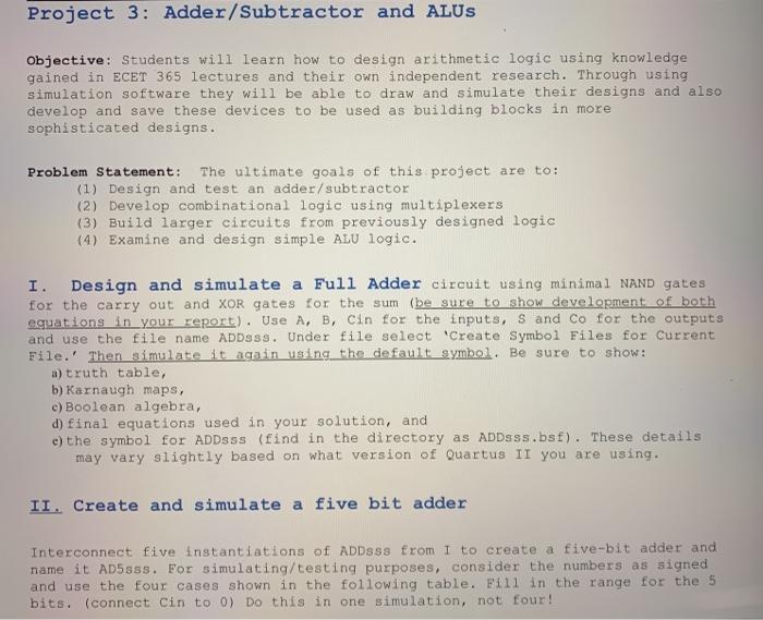
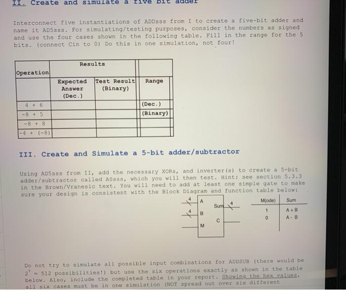
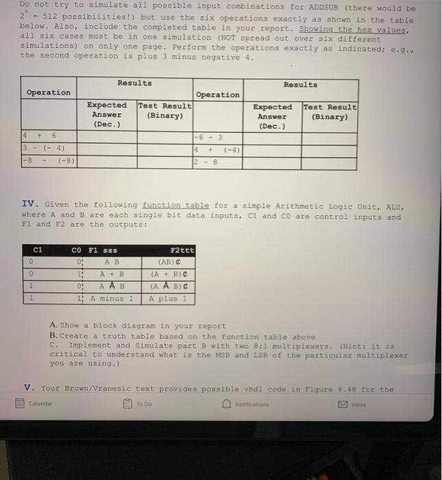
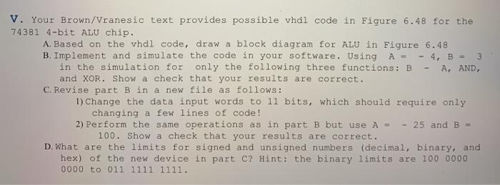
Project 3: Adder/Subtractor and ALUS Objective: Students will learn how to design arithmetic logic using knowledge gained in ECET 365 lectures and their own independent research. Through using simulation software they will be able to draw and simulate their designs and also develop and save these devices to be used as building blocks in more sophisticated designs. Problem Statement: The ultimate goals of this project are to: (1) Design and test an adder/subtractor (2) Develop combinational logic using multiplexers (3) Build larger circuits from previously designed logic (4) Examine and design simple ALU logic. I. Design and simulate a Full Adder circuit using minimal NAND gates for the carry out and XOR gates for the sum (be sure to show development of both equations in your report). Use A, B, Cin for the inputs, S and Co for the outputs and use the file name ADDsSs. Under file select "Create Symbol Files for Current File.' Then simulate it again using the default symbol. Be sure to show: a) truth table, b) Karnaugh maps, c) Boolean algebra, d) final equations used in your solution, and e) the symbol for ADDsss (find in the directory as ADDsss.bsf). These details may vary slightly based on what version of Quartus II you are using. II. Create and simulate a five bit adder Interconnect five instantiations of ADDSss from I to create a five-bit adder and name it AD58ss. For simulating/testing purposes, consider the numbers as signed and use the four cases shown in the following table. Fill in the range for the 5 bits. (connect Cin to 0) Do this in one simulation, not four! II. Create and simulate Ilve Interconnect five instantiations of ADDSSS from I to create a five-bit adder and name it ADSsss. For simulating/testing purposes, consider the numbers as signed and use the four cases shown in the following table. Fill in the range for the 5 bits. (connect Cin to 0) Do this in one simulation, not four! Results Operation Range Expected Answer (Dec.) Test Result (Binary) (Dec.) (Binary) -8 + 5 -8 + 8 - 4 + (-8) III. Create and Simulate a 5-bit adder/subtractor Using AD5858 from II, add the necessary XORs, and inverter(s) to create a 5-bit adder/subtractor called ASsss, which you will then test. Hint: see section 5.3.3 in the Brown/Vranesic text. You will need to add at least one simple gate to make sure your design is consistent with the Block Diagram and function table below: Mode) Sum Sun A+B A.B B 1 0 M Do not try to simulate all possible input combinations for ADDSUB (there would be 2 = 512 possibilities!) but use the six operations exactly as shown in the table below. Also, include the completed table in your report. Showing the hex values. all six cases must be in one simulation (NOT spread out over six different Do not try to simulate all possible input combinations for ADDSUB (there would be 2 = 512 possibilities!) but use the six operations exactly as shown in the table below. Also, include the completed table in your report. Showing the hex values, all six cases must be in one simulation (NOT spread out over six different simulations) on only one page. Perform the operations exactly as indicated; e... the second operation is plus 3 minus negative 4. Results Results Operation Operation Expected Answer (Dec.) Test Result (Binary) Expected Answer (Dec.) Test Result (Binary) 4 + 6 -63 3- 14 (-4) 1-8) 8 12 - B IV. Given the following function table for a simple Arithmetic Logic Unit, ALU, where A and B are each single bit data inputs, ci and co are control inputs and F1 and F2 are the outputs: ci 0 0 CO F1 SSS O: 1 + 0 A AB 1: A minus 1 F2ttt (ABC (A + B) (A ABC A plus 1 1 A. Show a block diagram in your report B. Create a truth table based on the function table above c. Implement and Simulate part B with two 8:1 multiplexers. (Hint: it is critical to understand what is the MSB and LSB of the particular multiplexer you are using.) V. Your Brown/Vranesic text provides possible vhdl code in Figure 6.48 for the Calendar To Do Noications 3 V. Your Brown/Vranesic text provides possible vhdl code in Figure 6.48 for the 74381 4-bit ALU chip. A. Based on the vhdi code, draw a block diagram for Alu in Figure 6.48 B. Implement and simulate the code in your software. Using A = - 4, B = in the simulation for only the following three functions: B - A, AND, and XOR. Show a check that your results are correct. C. Revise part B in a new file as follows: 1) Change the data input words to 11 bits, which should require only changing a few lines of code! 2) Perform the same operations as in part B but use A - - 25 and B = 100. Show a check that your results are correct. D. What are the limits for signed and unsigned numbers (decimal, binary, and hex) of the new device in part c? Hint: the binary limits are 100 0000 0000 to 011 1111 1111