Answered step by step
Verified Expert Solution
Question
1 Approved Answer
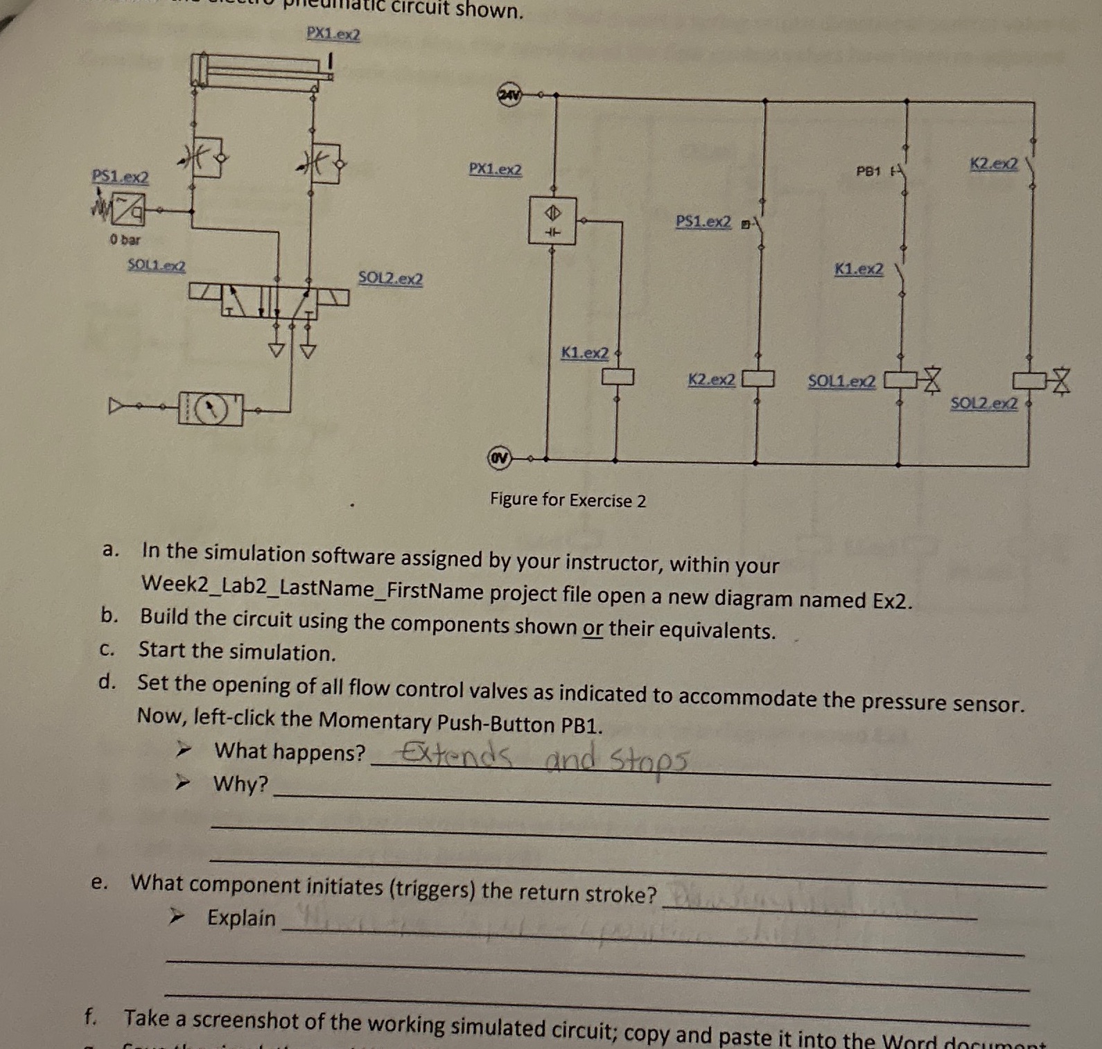
PS1.ex2 Z O bar SOL1.ex2 PX1.ex2 Circuit shown. HD SOL2.ex2 PX1.ex2 OV PS1.ex2 47 K2.ex2 PB1 A K1.ex2 K1.ex2 K2.ex2 SOL1.ex2 SOL2.ex2 Figure for

PS1.ex2 Z O bar SOL1.ex2 PX1.ex2 Circuit shown. HD SOL2.ex2 PX1.ex2 OV PS1.ex2 47 K2.ex2 PB1 A K1.ex2 K1.ex2 K2.ex2 SOL1.ex2 SOL2.ex2 Figure for Exercise 2 a. In the simulation software assigned by your instructor, within your Week2_Lab2_LastName_FirstName project file open a new diagram named Ex2. b. Build the circuit using the components shown or their equivalents. C. Start the simulation. d. Set the opening of all flow control valves as indicated to accommodate the pressure sensor. Now, left-click the Momentary Push-Button PB1. What happens? Extends and stops Why? e. What component initiates (triggers) the return stroke? Explain f. Take a screenshot of the working simulated circuit; copy and paste it into the Word
Step by Step Solution
There are 3 Steps involved in it
Step: 1

Get Instant Access to Expert-Tailored Solutions
See step-by-step solutions with expert insights and AI powered tools for academic success
Step: 2

Step: 3

Ace Your Homework with AI
Get the answers you need in no time with our AI-driven, step-by-step assistance
Get Started


