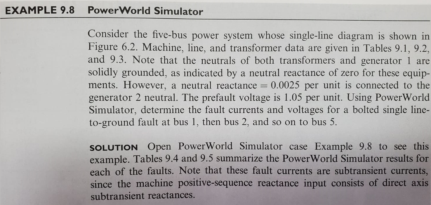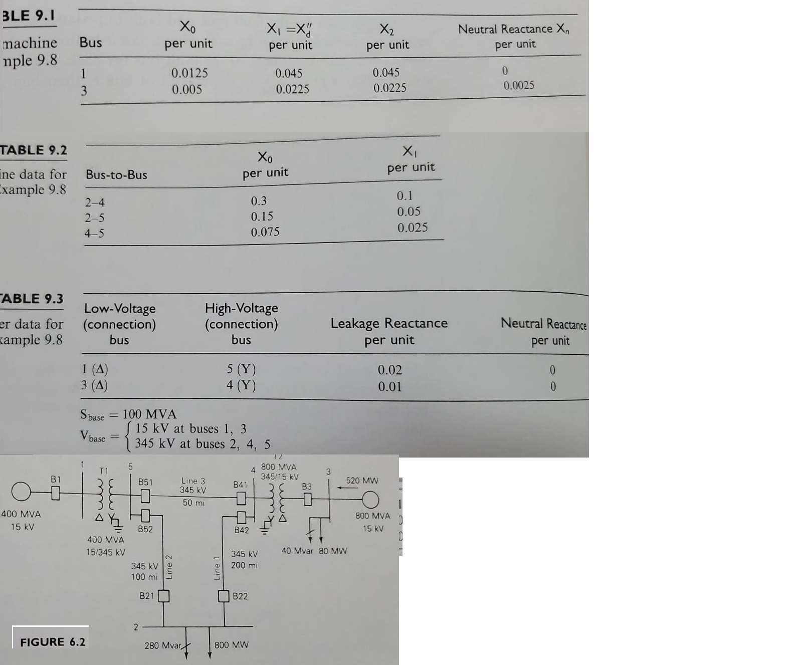


PW 9.62 Re-determine the Example 9.8 fault currents, except with a new line installed between buses 2 and 4. The parameters for this new line should be identical to those of the ex- isting line between buses 2 and 4. The new line is not mutually coupled to any other line. Are the fault currents larger or smaller than the Example 9.8 values? Re-determine the Example 9.8 fault currents, except with a second generator added at bus 3. The parameters for the new generator should be identical to those of the existing generator at bus 3. Are the fault currents larger or smaller than the Example 9.8 values? PW 9.63 EXAMPLE 9.8 PowerWorld Simulator Consider the five-bus power system whose single-line diagram is shown in Figure 6.2. Machine, line, and transformer data are given in Tables 9.1, 9.2, and 9.3. Note that the neutrals of both transformers and generator 1 are solidly grounded, as indicated by a neutral reactance of zero for these equip- ments. However, a neutral reactance = 0.0025 per unit is connected to the generator 2 neutral. The prefault voltage is 1.05 per unit. Using Power World Simulator, determine the fault currents and voltages for a bolted single line- to-ground fault at bus 1, then bus 2, and so on to bus 5. SOLUTION Open PowerWorld Simulator case Example 9.8 to see this example. Tables 9.4 and 9.5 summarize the PowerWorld Simulator results for each of the faults. Note that these fault currents are subtransient currents, since the machine positive-sequence reactance input consists of direct axis subtransient reactances. BLE 9.1 Xo Xi = X5 X2 Neutral Reactance Xn Bus per unit machine nple 9.8 per unit per unit per unit 1 3 0.0125 0.005 0.045 0.0225 0.045 0.0225 0 0.0025 TABLE 9.2 Xo X Bus-to-Bus per unit per unit ine data for Example 9.8 24 2-5 4-5 0.3 0.15 0.075 0.1 0.05 0.025 ABLE 9.3 Low-Voltage (connection) bus High-Voltage (connection) bus er data for kample 9.8 Leakage Reactance Neutral Reactance per unit per unit 1 (1) 3 (A) 5 (Y) 4 (Y) 0.02 0.01 0 0 S base = 100 MVA 15 kV at buses 1, 3 Vbase = 345 kV at buses 2, 4, 5 1 5 T1 4 12 800 MVA 345/15 kV B3 3 B1 B51 B41 520 MW Line 3 345 KV 50 mi itzulo 400 MVA 15 kV DO AK 800 MVA 15 kV B52 B42 400 MVA 15/345 kV 40 Mvar 80 MW 345 kV 200 mi 345 kV 100 mi Line 2 Line B21 B22 2 FIGURE 6.2 280 Mvar 800 MW PW 9.62 Re-determine the Example 9.8 fault currents, except with a new line installed between buses 2 and 4. The parameters for this new line should be identical to those of the ex- isting line between buses 2 and 4. The new line is not mutually coupled to any other line. Are the fault currents larger or smaller than the Example 9.8 values? Re-determine the Example 9.8 fault currents, except with a second generator added at bus 3. The parameters for the new generator should be identical to those of the existing generator at bus 3. Are the fault currents larger or smaller than the Example 9.8 values? PW 9.63 EXAMPLE 9.8 PowerWorld Simulator Consider the five-bus power system whose single-line diagram is shown in Figure 6.2. Machine, line, and transformer data are given in Tables 9.1, 9.2, and 9.3. Note that the neutrals of both transformers and generator 1 are solidly grounded, as indicated by a neutral reactance of zero for these equip- ments. However, a neutral reactance = 0.0025 per unit is connected to the generator 2 neutral. The prefault voltage is 1.05 per unit. Using Power World Simulator, determine the fault currents and voltages for a bolted single line- to-ground fault at bus 1, then bus 2, and so on to bus 5. SOLUTION Open PowerWorld Simulator case Example 9.8 to see this example. Tables 9.4 and 9.5 summarize the PowerWorld Simulator results for each of the faults. Note that these fault currents are subtransient currents, since the machine positive-sequence reactance input consists of direct axis subtransient reactances. BLE 9.1 Xo Xi = X5 X2 Neutral Reactance Xn Bus per unit machine nple 9.8 per unit per unit per unit 1 3 0.0125 0.005 0.045 0.0225 0.045 0.0225 0 0.0025 TABLE 9.2 Xo X Bus-to-Bus per unit per unit ine data for Example 9.8 24 2-5 4-5 0.3 0.15 0.075 0.1 0.05 0.025 ABLE 9.3 Low-Voltage (connection) bus High-Voltage (connection) bus er data for kample 9.8 Leakage Reactance Neutral Reactance per unit per unit 1 (1) 3 (A) 5 (Y) 4 (Y) 0.02 0.01 0 0 S base = 100 MVA 15 kV at buses 1, 3 Vbase = 345 kV at buses 2, 4, 5 1 5 T1 4 12 800 MVA 345/15 kV B3 3 B1 B51 B41 520 MW Line 3 345 KV 50 mi itzulo 400 MVA 15 kV DO AK 800 MVA 15 kV B52 B42 400 MVA 15/345 kV 40 Mvar 80 MW 345 kV 200 mi 345 kV 100 mi Line 2 Line B21 B22 2 FIGURE 6.2 280 Mvar 800 MW


