

Question: Q: Principles of Electronics 0241 for the eld 32 grid is used to control the flow of electrons between cathode and plate. The others are
Q:
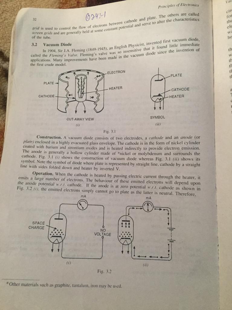
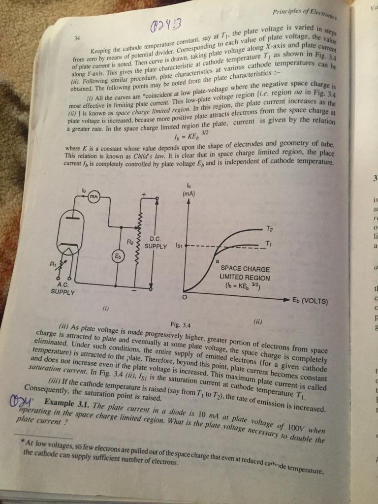
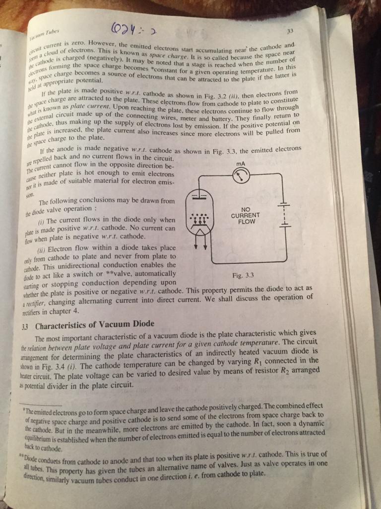
Principles of Electronics 0241 for the eld 32 grid is used to control the flow of electrons between cathode and plate. The others are called screen grids and are generally held at some constant potential and serve to alter the characteristics of the tube. 3.2 Vacuum Diode he = "w" mwuuul th applications. Many improvements have been made in the vacuum diode since the invention of the first crude model. n. 1904, Sir J.A. Fleming (1849-1945), an English Physicist, invented first vacuum diode, applied the Fleming's Valve. Fleming's valve was so insensitive that it found little immediate ELECTRON -PLATE PLATE HEATER CATHODE HEATER CATHODE SYMBOL CUT AWAY VIEW fi) Fig. 3.1 Construction. A vacuum diode consists of two electrodes, a cathode and an anode (or plare) enclosed in a highly evacuated glass envelope. The cathode is in the form of nickel cylinder coated with barium and strontium oxides and is heated indirectly to provide electron emission. The anode is generally a hollow cylinder made of nickel or molybdenum and surrounds the cathode. Fig. 3.1 (i) shows the construction of vacuum diode whereas Fig. 3.1 (ii) shows its symbol. Note the symbol of diode where plate is represented by straight line, cathode by a straight line with sides folded down and heater by inverted V. Operation. When the cathode is heated by passing electric current through the heater, it emits a large number of electrons. The behaviour of these emitted electrons will depend upon the anode potential w.r.l. cathode. If the anode is at zero potential wr.l. cathode as shown in Fig. 3.2 (i). the emitted electrons simply cannot go to plate as the latter is neutral. Therefore, MA mA - SPACE CHARGE NO VOLTAGE ED to) Fig. 3.2 *Other materials such as graphite, tantalum. iron may be used. va Principles of Electronics 02413 steps 34 from zero by means of potential divider. Corresponding to each value of plate voltage, the value Keeping the cathode temperature constant, say ar 7. the plate voltage is varied in along Y-axis. This gives the plate characteristic at cathode temperature 7, as shown in Fig. 34 of plate current is noted. Then curve is drawn, taking plate voltage along X-axis and plate current (ii). Following similar procedure, plate characteristics at various cathode temperatures can be obtained. The following points may be noted from the plate characteristics :- most effective in limiting plate current. This low-plate voltage region i.e. region oa in Fig. 3.4 All the curves are "coincident at low plate-voltage where the negative space chargej plate voltage is increased, because more positive plate attracts electrons from the space charge at is is known as space charge limited region. In this region, the plate current increases as c a greater rate. In the space charge limited region the plate, current is given by the relation 1 = KE, where K is a constant whose value depends upon the shape of electrodes and geometry of tube. This relation is known as Child's law. It is clear that in space charge limited region, the place current I, is completely controlled by plate voltage E, and is independent of cathode temperature. 3/2 3 (MA) is 411 1 2 lo R2 D.C. SUPPLY IS1 TH a a SPACE CHARGE LIMITED REGION (Ib = KE, 32 A.C. SUPPLY th Eb (VOLTS) 9 Fig. 3.4 (ii) As plate voltage is made progressively higher greater portion of electrons from space charge is attracted to plate and eventually at some plate voltage, the space charge is completely eliminated. Under such conditions, the entire supply of emitted electrons (for a given cathode temperature) is attracted to the plate. Therefore, beyond this point, plate current becomes constant and does not increase even if the plate voltage is increased. This maximum plate current is called saturation current. In Fig. 3.4 (ii), Is is the saturation current at cathode temperature T (iii) If the cathode temperature is raised (say from T, to Ty), the rate of emission is increased. Consequently, the saturation point is raised. t operating in the space charge limited region. What is the plate voltage necessary to double the plate current * At low voltages, so few electrons are pulled out of the space charge that even at reduced cathode temperature. the cathode can supply sufficient number of electrons. 624:2 33 he cathode I I current is zero. However, the emitted electrons start accumulating near the cathode and a cloud of electrons. This is known as space charge. It is so called because the space near Is charged (negatively). It may be noted that a stage is reached when the number of wce change becomes a source of electrons that can be attracted to the plate if the latter is actros forming the space charge becomes "constant for a given operating temperature. In this old at appropriate potential. the plates made positive wr.l. cathode as shown in Fig. 3.2 (ii), then electrons from space charge are attracted to the plate. These electrons flow from cathode to plate to constitute what is known as plate current. Upon reaching the plate, these electrons continue to flow through she cathode, thus making up the supply of electrons lost by emission. If the positive potential on the extemal circuit made up of the connecting wires, meter and battery. They finally return to the space charge to the plate. the plate is increased, the plate current also increases since more electrons will be pulled from se repelled back and no current flows in the circuit. The current cannot flow in the opposite direction be- mA ause neither plate is hot enough to emit electrons ar it is made of suitable material for electron emis- If the anode is made negative w...t cathode as shown in Fig. 3.3. the emitted electrons it The following conclusions may be drawn from the diode valve operation : NO (i) The current flows in the diode only when CURRENT FLOW plate is made positive w... cathode. No current can few when plate is negative wr.1. cathode. () Electron flow within a diode takes place only from cathode to plate and never from plate to cathode. This unidirectional conduction enables the fode to act like a switch or **valve, automatically Fig. 3.3 starting or stopping conduction depending upon whether the plate is positive or negative w.r.l. cathode. This property permits the diode to act as a rectifier, changing alternating current into direct current. We shall discuss the operation of rectifiers in chapter 4. 33 Characteristics of Vacuum Diode The most important characteristic of a vacuum diode is the plate characteristic which gives the relation between plate voltage and plate current for a given cathode temperature. The circuit arrangement for determining the plate characteristics of an indirectly heated vacuum diode is shown in Fig. 3.4 (i). The cathode temperature can be changed by varying Ri connected in the heater circuit. The plate voltage can be varied to desired value by means of resistor R2 arranged as potential divider in the plate circuit. *The emitted electrons go to form space charge and leave the cathode positively charged. The combined effect of negative space charge and positive cathode is to send some of the electrons from space charge back to the cathode. But in the meanwhile, more electrons are emitted by the cathode. In fact, soon a dynamic equilibrium is established when the number of electrons emitted is equal to the number of electrons attracted back to cathode **Dude conduets from cathode to anode and that too when its plate is positive w... cathode. This is true of all tubes. This property has given the tubes an alternative name of valves. Just as valve operates in one direction, similarly vacuum tubes conduct in one direction i. e. from cathode to plate
Step by Step Solution
There are 3 Steps involved in it

Get step-by-step solutions from verified subject matter experts