Answered step by step
Verified Expert Solution
Link Copied!

Question

1 Approved Answer

Q1. Line 46, Which vector stores the ISR address? Q2. Line 47, What happens after Timer_A ISR returns? Q3. Which line numbers would be Setup

Q1. Line 46, Which vector stores the ISR address?

Q2. Line 47, What happens after Timer_A ISR returns?

Q3. Which line numbers would be Setup if Arduino style was used?

Q4. What happened to the Loop section that would be in Arduino code style?image text in transcribed

#include 24. 25 int main(void 26 L 27 28 29 30 31 32 WDTCTL WDTPW | WDTHOLD onfigure GPIO P1DIR IBITO; P1OUT IBITO P1.0 outpu P1.0 hig Disable the GPI0 power-on default high-impedance mode to activat // previously configured port setting PM5CTL0 &=-LOCKLPM5 34. 35 36 37 38 TACCRO interrupt enabled TAOCCR0 50000 40 41 42 43 bis_SR_registerCLPM3_bits I GIE); no_operationO; Go to Sleep: Enter LPM3 w/interru For debu 45 46#pragma vector -TIMERO_A0-VECTOR 47 __interrupt void Timer_A (void) 48 49 50 P1OUT ABIT0; 51 Timer A0 interrupt service routine #include 24. 25 int main(void 26 L 27 28 29 30 31 32 WDTCTL WDTPW | WDTHOLD onfigure GPIO P1DIR IBITO; P1OUT IBITO P1.0 outpu P1.0 hig Disable the GPI0 power-on default high-impedance mode to activat // previously configured port setting PM5CTL0 &=-LOCKLPM5 34. 35 36 37 38 TACCRO interrupt enabled TAOCCR0 50000 40 41 42 43 bis_SR_registerCLPM3_bits I GIE); no_operationO; Go to Sleep: Enter LPM3 w/interru For debu 45 46#pragma vector -TIMERO_A0-VECTOR 47 __interrupt void Timer_A (void) 48 49 50 P1OUT ABIT0; 51 Timer A0 interrupt service routine

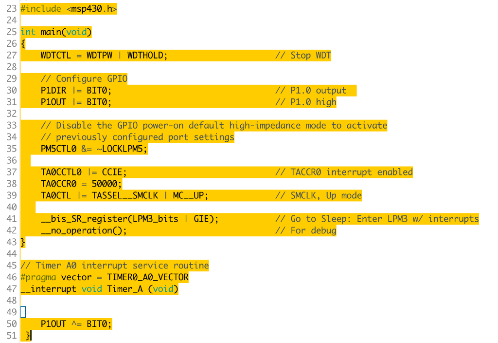
Step by Step Solution

There are 3 Steps involved in it

Step: 1

blur-text-image

Get Instant Access to Expert-Tailored Solutions

See step-by-step solutions with expert insights and AI powered tools for academic success

Step: 2

blur-text-image

Step: 3

blur-text-image

Ace Your Homework with AI

Get the answers you need in no time with our AI-driven, step-by-step assistance

Get Started

Students also viewed these Databases questions