Answered step by step
Verified Expert Solution
Question
1 Approved Answer
Q2. Suppose the input voltage x(t) and output y(t) of a continuous time system (RLC filter circuit) are related by the ordinary differential equation defined
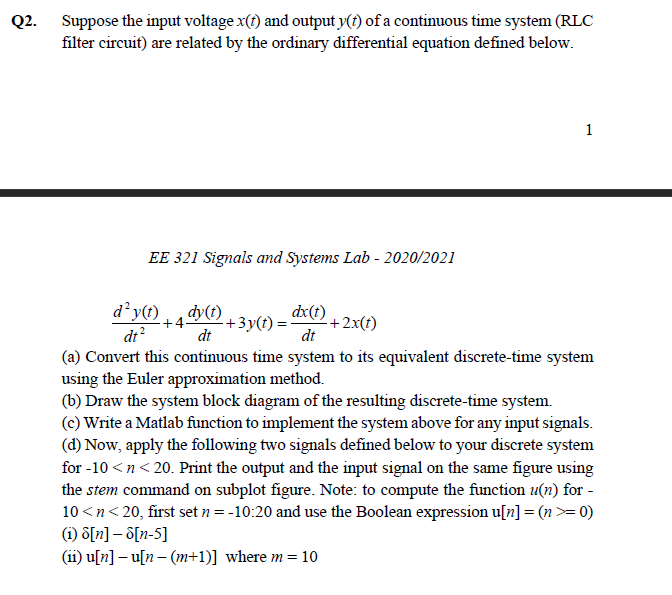
Q2. Suppose the input voltage x(t) and output y(t) of a continuous time system (RLC filter circuit) are related by the ordinary differential equation defined below. 1 EE 321 Signals and Systems Lab - 2020/2021 dy(t) dy(t) dx(t) +4- +3y(t) = +2x(t) dt? dt dt (a) Convert this continuous time system to its equivalent discrete-time system using the Euler approximation method. (b) Draw the system block diagram of the resulting discrete-time system. (c) Write a Matlab function to implement the system above for any input signals. (d) Now, apply the following two signals defined below to your discrete system for -10 =0) (1) [n] - [n-5] (11) u[n] - u[n-(m+1)] where m= = 10 Q2. Suppose the input voltage x(t) and output y(t) of a continuous time system (RLC filter circuit) are related by the ordinary differential equation defined below. 1 EE 321 Signals and Systems Lab - 2020/2021 dy(t) dy(t) dx(t) +4- +3y(t) = +2x(t) dt? dt dt (a) Convert this continuous time system to its equivalent discrete-time system using the Euler approximation method. (b) Draw the system block diagram of the resulting discrete-time system. (c) Write a Matlab function to implement the system above for any input signals. (d) Now, apply the following two signals defined below to your discrete system for -10 =0) (1) [n] - [n-5] (11) u[n] - u[n-(m+1)] where m= = 10<><>
Step by Step Solution
There are 3 Steps involved in it
Step: 1
Get Instant Access to Expert-Tailored Solutions
See step-by-step solutions with expert insights and AI powered tools for academic success
Step: 2
Step: 3
Ace Your Homework with AI
Get the answers you need in no time with our AI-driven, step-by-step assistance
Get Started