

Question: Q2.2 5 Points Consider another circuit that is referred to as MOD2 and whose interface is as shown below: B B X4 Save Answer
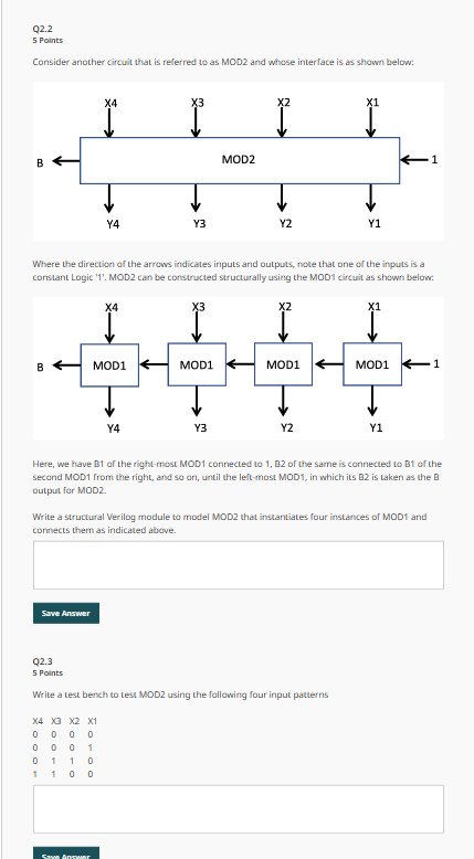
Q2.2 5 Points Consider another circuit that is referred to as MOD2 and whose interface is as shown below: B B X4 Save Answer Y4 X4 MOD1 X4 X3 X2 X1 0000 0001 011 0 110 0 Save Answer X3 Y4 Y3 Where the direction of the arrows indicates inputs and outputs, note that one of the inputs is a constant Logic '1'. MOD2 can be constructed structurally using the MOD1 circuit as shown below: X3 MOD1 MOD2 Y3 X2 Y2 X2 MOD1 Y2 X1 Q2.3 5 Points Write a test bench to test MOD2 using the following four input patterns Y1 X1 Here, we have B1 of the right-most MOD1 connected to 1, B2 of the same is connected to B1 of the second MOD1 from the right, and so on, until the left-most MOD1, in which its B2 is taken as the B output for MOD2. Write a structural Verilog module to model MOD2 that instantiates four instances of MOD1 and connects them as indicated above. 1 MOD1 1 Y1
Step by Step Solution
3.36 Rating (149 Votes )
There are 3 Steps involved in it
1 verilog module MOD1A B1 B2 input A output B1 B2 assign B1 A assign B2 A endmodule module MO... View full answer

Get step-by-step solutions from verified subject matter experts