Question
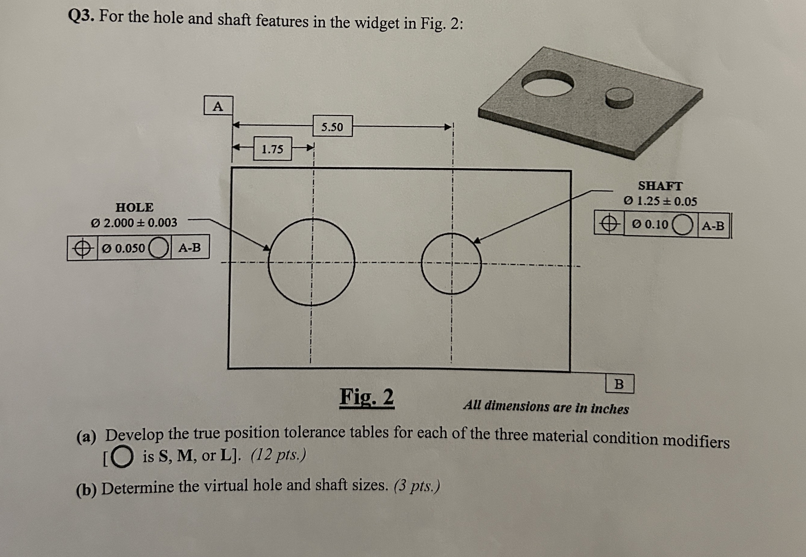
Q3. For the hole and shaft features in the widget in Fig. 2: HOLE 02.000 0.003 0.050 A-B A 1.75 5.50 Fig. 2 SHAFT

Q3. For the hole and shaft features in the widget in Fig. 2: HOLE 02.000 0.003 0.050 A-B A 1.75 5.50 Fig. 2 SHAFT 0 1.25 0.05 00.10A-B B All dimensions are in inches (a) Develop the true position tolerance tables for each of the three material condition modifiers [O is S, M, or L]. (12 pts.) (b) Determine the virtual hole and shaft sizes. (3 pts.)
Step by Step Solution
There are 3 Steps involved in it
Step: 1

Get Instant Access to Expert-Tailored Solutions
See step-by-step solutions with expert insights and AI powered tools for academic success
Step: 2

Step: 3

Ace Your Homework with AI
Get the answers you need in no time with our AI-driven, step-by-step assistance
Get StartedRecommended Textbook for
Statistics For Business & Economics
Authors: David R. Anderson, Dennis J. Sweeney, Thomas A. Williams, Jeffrey D. Camm, James J. Cochran
13th Edition
1305585313, 978-1305585317
Students also viewed these Mechanical Engineering questions
Question
Answered: 1 week ago
Question
Answered: 1 week ago
Question
Answered: 1 week ago
Question
Answered: 1 week ago
Question
Answered: 1 week ago
Question
Answered: 1 week ago
Question
Answered: 1 week ago
Question
Answered: 1 week ago
Question
Answered: 1 week ago
Question
Answered: 1 week ago
Question
Answered: 1 week ago
Question
Answered: 1 week ago
Question
Answered: 1 week ago
Question
Answered: 1 week ago
Question
Answered: 1 week ago
Question
Answered: 1 week ago
Question
Answered: 1 week ago
Question
Answered: 1 week ago
Question
Answered: 1 week ago
Question
Answered: 1 week ago
View Answer in SolutionInn App


