Answered step by step
Verified Expert Solution
Question
1 Approved Answer
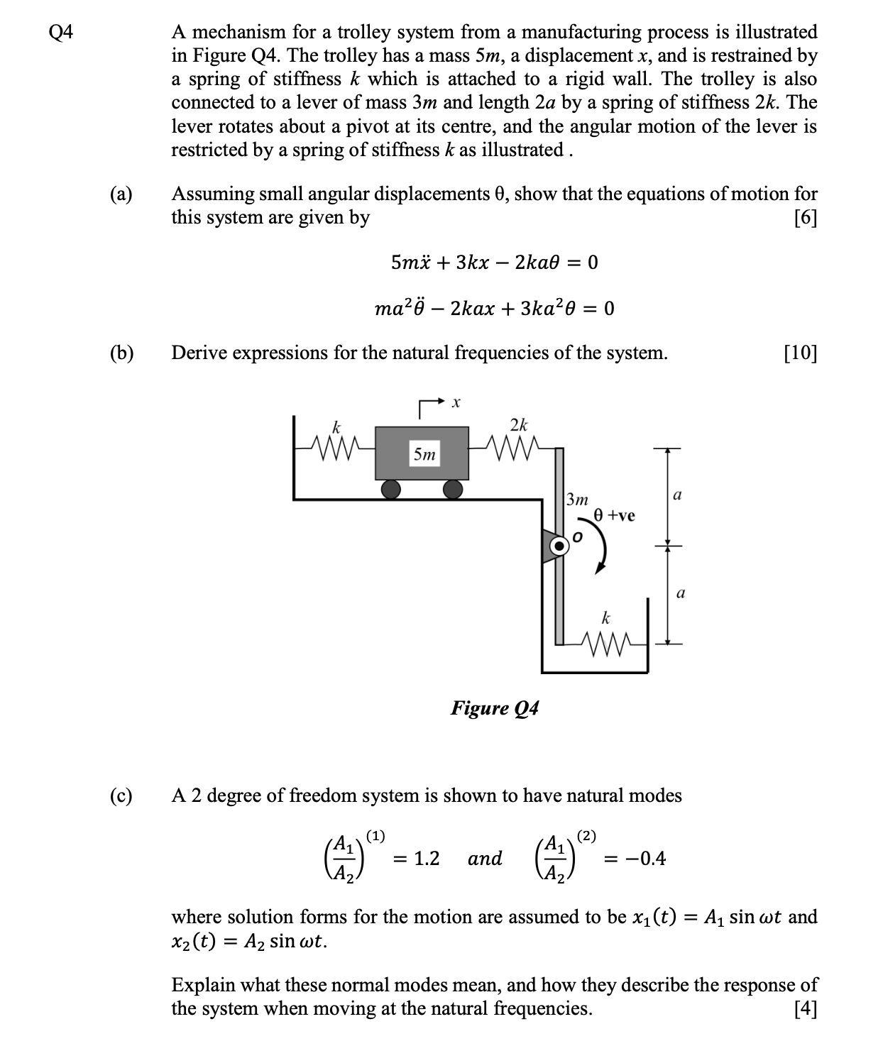
Q4 (a) (b) (c) A mechanism for a trolley system from a manufacturing process is illustrated in Figure Q4. The trolley has a mass

Q4 (a) (b) (c) A mechanism for a trolley system from a manufacturing process is illustrated in Figure Q4. The trolley has a mass 5m, a displacement x, and is restrained by a spring of stiffness k which is attached to a rigid wall. The trolley is also connected to a lever of mass 3m and length 2a by a spring of stiffness 2k. The lever rotates about a pivot at its centre, and the angular motion of the lever is restricted by a spring of stiffness k as illustrated. Assuming small angular displacements 0, show that the equations of motion for this system are given by [6] ma - 2kax + 3ka0 Derive expressions for the natural frequencies of the system. | 5mx + 3kx - 2ka0 = 0 A 5m X 2k M Figure Q4 = 1.2 and = (A A 3m 0 0 +ve A 2 degree of freedom system is shown to have natural modes (1) (2) a a k inft = -0.4 [10] where solution forms for the motion are assumed to be x (t) = A sin wt and x (t) = A sin wt. Explain what these normal modes mean, and how they describe the the system when moving at the natural frequencies. response of [4]
Step by Step Solution
There are 3 Steps involved in it
Step: 1
a To derive the equations of motion for the given system we can consider the forces acting on each m...
Get Instant Access to Expert-Tailored Solutions
See step-by-step solutions with expert insights and AI powered tools for academic success
Step: 2

Step: 3

Ace Your Homework with AI
Get the answers you need in no time with our AI-driven, step-by-step assistance
Get Started


