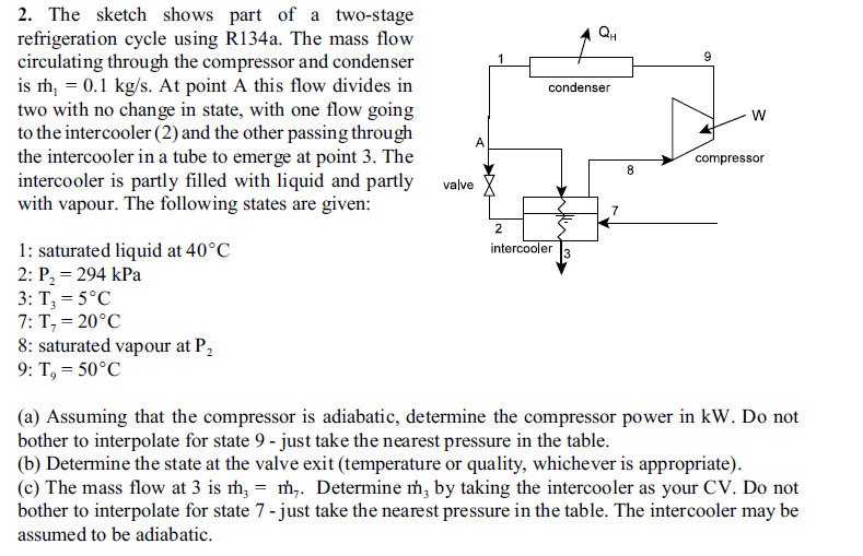
QH 9 condenser 2. The sketch shows part of a two-stage refrigeration cycle using R134a. The mass flow circulating through the compressor and condenser is m, = 0.1 kg/s. At point A this flow divides in two with no change in state, with one flow going to the intercooler (2) and the other passing through the intercooler in a tube to emerge at point 3. The intercooler is partly filled with liquid and partly valve with vapour. The following states are given: W A compressor 8 7 2 intercooler 3 1: saturated liquid at 40C 2: P = 294 kPa 3: T, = 5C 7: T, = 20C 8: saturated vapour at P, 9: T, = 50C (a) Assuming that the compressor is adiabatic, determine the compressor power in kW. Do not bother to interpolate for state 9 - just take the nearest pressure in the table. (b) Determine the state at the valve exit (temperature or quality, whichever is appropriate). (c) The mass flow at 3 is m = m. Determine m, by taking the intercooler as your CV. Do not bother to interpolate for state 7 - just take the nearest pressure in the table. The intercooler may be assumed to be adiabatic. QH 9 condenser 2. The sketch shows part of a two-stage refrigeration cycle using R134a. The mass flow circulating through the compressor and condenser is m, = 0.1 kg/s. At point A this flow divides in two with no change in state, with one flow going to the intercooler (2) and the other passing through the intercooler in a tube to emerge at point 3. The intercooler is partly filled with liquid and partly valve with vapour. The following states are given: W A compressor 8 7 2 intercooler 3 1: saturated liquid at 40C 2: P = 294 kPa 3: T, = 5C 7: T, = 20C 8: saturated vapour at P, 9: T, = 50C (a) Assuming that the compressor is adiabatic, determine the compressor power in kW. Do not bother to interpolate for state 9 - just take the nearest pressure in the table. (b) Determine the state at the valve exit (temperature or quality, whichever is appropriate). (c) The mass flow at 3 is m = m. Determine m, by taking the intercooler as your CV. Do not bother to interpolate for state 7 - just take the nearest pressure in the table. The intercooler may be assumed to be adiabatic


