Answered step by step
Verified Expert Solution
Question
1 Approved Answer
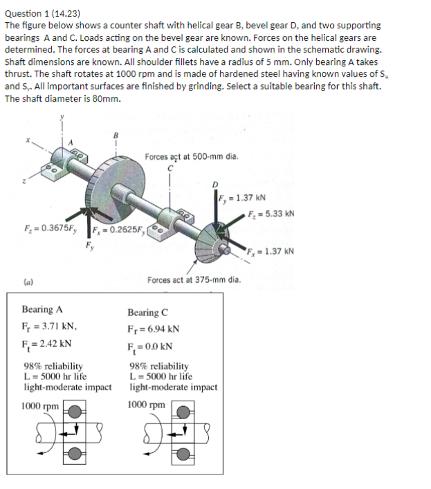
Question 1 (14.23) The figure below shows a counter shaft with helical gear B, bevel gear D, and two supporting bearings A and C.

Question 1 (14.23) The figure below shows a counter shaft with helical gear B, bevel gear D, and two supporting bearings A and C. Loads acting on the bevel gear are known. Forces on the helical gears are determined. The forces at bearing A and C is calculated and shown in the schematic drawing. Shaft dimensions are known. All shoulder fillets have a radius of 5 mm. Only bearing A takes thrust. The shaft rotates at 1000 rpm and is made of hardened steel having known values of S. and S,. All important surfaces are finished by grinding. Select a suitable bearing for this shaft. The shaft diameter is 80mm. F = 0.3675Fy F. 0.2625Fy Forces act at 500-mm dia. -1.37 kN F=5.33 kN (a) Bearing A Fr=3.71 kN, F = 2.42 kN 98% reliability L = 5000 hr life light-moderate impact 1000 rpm Forces act at 375-mm dia. Bearing C Fr=6.94 kN F = 0.0 kN 98% reliability L = 5000 hr life light-moderate impact 1000 rpm F = 1.37 kN
Step by Step Solution
There are 3 Steps involved in it
Step: 1

Get Instant Access to Expert-Tailored Solutions
See step-by-step solutions with expert insights and AI powered tools for academic success
Step: 2

Step: 3

Ace Your Homework with AI
Get the answers you need in no time with our AI-driven, step-by-step assistance
Get Started


