Answered step by step
Verified Expert Solution
Question
1 Approved Answer
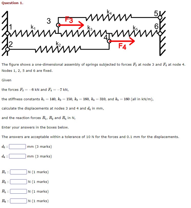
Question 1. 3 F3 www F4 The figure shows a one-dimensional assembly of springs subjected to forces F3 at node 3 and F at

Question 1. 3 F3 www F4 The figure shows a one-dimensional assembly of springs subjected to forces F3 at node 3 and F at node 4. Nodes 1, 2, 5 and 6 are fixed. Given the forces F3-6 kN and F = -7 kN, the stiffness constants k = 140, k = 150, k3 = 160, k = 310, and ks == 160 (all in kN/m), calculate the displacements at nodes 3 and 4 and d in mm, and the reaction forces R, R and R in N, Enter your answers in the boxes below. The answers are acceptable within a tolerance of 10 N for the forces and 0.1 mm for the displacements. d3: mm (3 marks) ds mm (3 marks) : N (1 marks) R: N (1 marks) R: N (1 marks) R6: N (1 marks)
Step by Step Solution
There are 3 Steps involved in it
Step: 1

Get Instant Access to Expert-Tailored Solutions
See step-by-step solutions with expert insights and AI powered tools for academic success
Step: 2

Step: 3

Ace Your Homework with AI
Get the answers you need in no time with our AI-driven, step-by-step assistance
Get Started


