

Question: QUESTION 1 (a) The column in Figure 1 is fixed at both ends and under a compressive load. Find the critical load for buckling
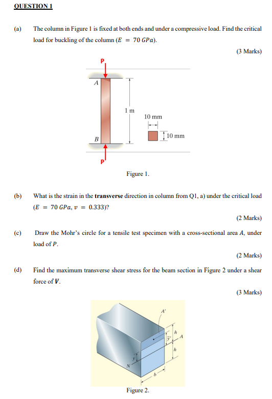
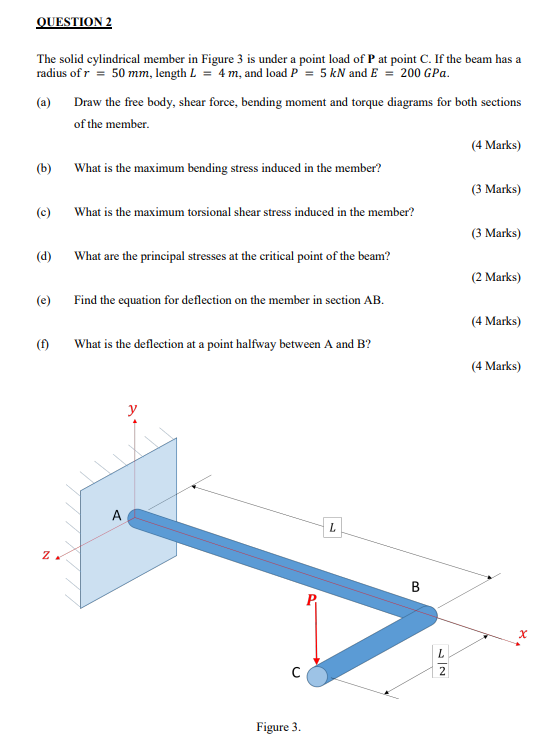
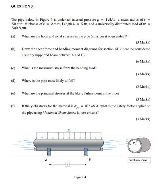
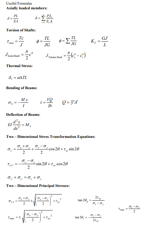
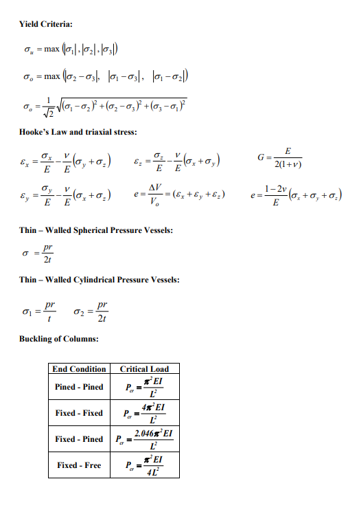
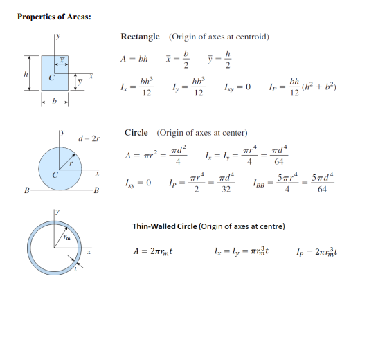
QUESTION 1 (a) The column in Figure 1 is fixed at both ends and under a compressive load. Find the critical load for buckling of the column (E = 70 GPa). (3 Marks) (b) (c) (d) A B 1 m 10 mm 10 mm Figure 1. What is the strain in the transverse direction in column from Q1, a) under the critical load (E = 70 GPa, v = 0.333)? (2 Marks) Draw the Mohr's circle for a tensile test specimen with a cross-sectional area A, under load of P. (2 Marks) Find the maximum transverse shear stress for the beam section in Figure 2 under a shear force of V. Figure 2. (3 Marks) QUESTION 2 The solid cylindrical member in Figure 3 is under a point load of P at point C. If the beam has a radius of r = 50 mm, length L = 4 m, and load P = 5 kN and E = 200 GPa. (a) Draw the free body, shear force, bending moment and torque diagrams for both sections of the member. (4 Marks) (b) What is the maximum bending stress induced in the member? (3 Marks) (c) What is the maximum torsional shear stress induced in the member? (3 Marks) (d) What are the principal stresses at the critical point of the beam? (2 Marks) (e) Find the equation for deflection on the member in section AB. (4 Marks) (f) What is the deflection at a point halfway between A and B? (4 Marks) . y Figure 3. L B 22 x QUESTION 3 The pipe below in Figure 4 is under an internal pressure p = 1 MPa, a mean radius of r = 50 mm, thickness of t = 2 mm, Length L = 5 m, and a universally distributed load of w = 500 N/m. (a) What are the hoop and axial stresses in the pipe (consider it open ended)? (3 Marks) (b) Draw the shear force and bending moment diagrams for section AB (it can be considered a simply supported beam between A and B). (6 Marks) (c) What is the maximum stress from the bending load? (3 Marks) (d) Where is the pipe most likely to fail? (2 Marks) (e) What are the principal stresses at the likely failure point in the pipe? (3 Marks) (f) If the yield stress for the material is yp = 187 MPa, what is the safety factor applied to the pipe using Maximum Shear Stress failure criteria? (3 Marks) A W B Section View L Figure 4. Useful Formulas Axially loaded members: PL EA Torsion of Shafts: T max Tc 8="PL EA TL TL GJ - K = = JG JG Js Solid Shaft JT = Tubular Shaft Thermal Stress: 8 =ATL Bending of Beams: My x = VQ Ib Q=y'A' Deflection of Beams: dy =Mx dx Two-Dimensional Stress Transformation Equations: cos 20+ sin 20 xy 2 2 - -sin 20+xy' cos 20 2 + = 0 + 0, Two-Dimensional Principal Stresses: 2 tan 20p + 01.2 2 2 = 25x3 x-y 2 tan 20 = 25xy Tmax 2 Yield Criteria: = max = max (01102103) (02-03|, |01-03, 0-02) = 1/2 (0 2) +( 3) +(03-0) Hooke's Law and triaxial stress: Ex V x = 0 x 1 / (y + ((0, +) = E E y E V . E E c = A = (6x+8 +8) V Thin-Walled Spherical Pressure Vessels: pr 21 Thin - Walled Cylindrical Pressure Vessels: pr pr 2t Buckling of Columns: End Condition Critical Load ' Pined - Pined 4% El Fixed - Fixed P= 2.0467. Fixed - Pined P = ' Fixed - Free 4 E G e= 2(1+v) 1-2 (0+0+0) E Properties of Areas: Rectangle (Origin of axes at centroid) A = bh x= y= 2 h 2 V bh3 1x = hb3 ly 12 12 Ixy = 0 Ip = bh (h + b) d=2r Circle (Origin of axes at center) A = r #d #d4 = 4 1x = ly = 4 64 x 1xy=0 Ip B- B #d4 32 5r4 5 d4 IBB 4 64 Thin-Walled Circle (Origin of axes at centre) A = 2rmt Ip = 2rt
Step by Step Solution
There are 3 Steps involved in it
Solution 1 1a The column is fixed at both ends which means we can use Eulers buckling formula for a column that is fixed at both ends Pcr 2 EIL 2 Where P cr Critical load E Modulus of Elasticity 70 GP... View full answer

Get step-by-step solutions from verified subject matter experts