Answered step by step
Verified Expert Solution
Question
1 Approved Answer
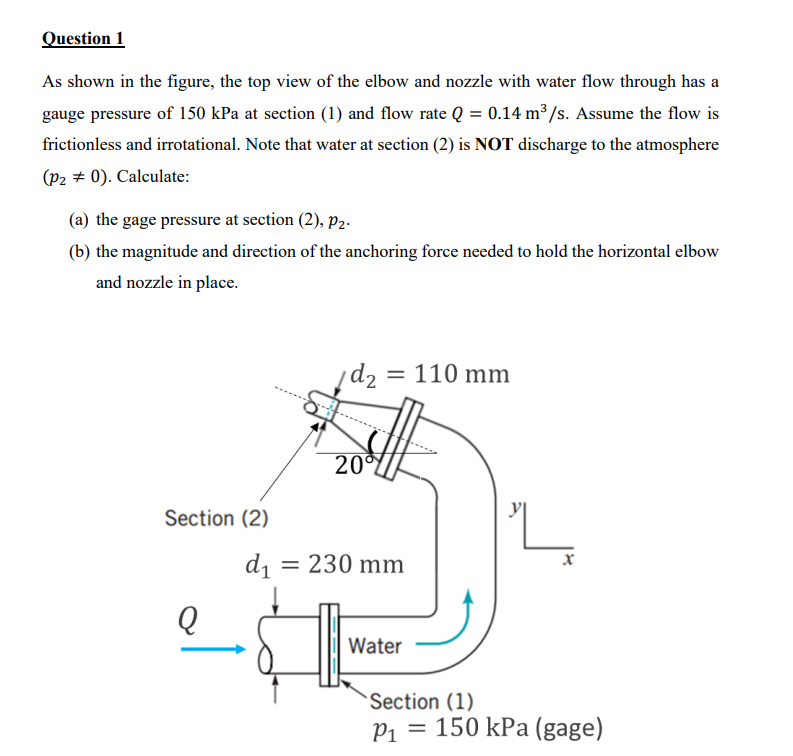
Question 1 As shown in the figure, the top view of the elbow and nozzle with water flow through has a gauge pressure of

Question 1 As shown in the figure, the top view of the elbow and nozzle with water flow through has a gauge pressure of 150 kPa at section (1) and flow rate Q = 0.14 m/s. Assume the flow is frictionless and irrotational. Note that water at section (2) is NOT discharge to the atmosphere (P20). Calculate: (a) the gage pressure at section (2), Pz. (b) the magnitude and direction of the anchoring force needed to hold the horizontal elbow and nozzle in place. Section (2) Q d2 = 110 mm 20% d = 230 mm x Water Section (1) P = 150 kPa (gage)
Step by Step Solution
There are 3 Steps involved in it
Step: 1

Get Instant Access to Expert-Tailored Solutions
See step-by-step solutions with expert insights and AI powered tools for academic success
Step: 2

Step: 3

Ace Your Homework with AI
Get the answers you need in no time with our AI-driven, step-by-step assistance
Get Started


