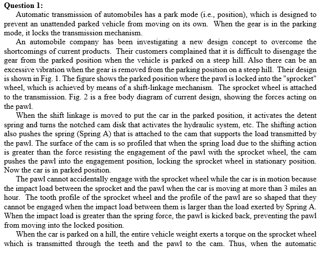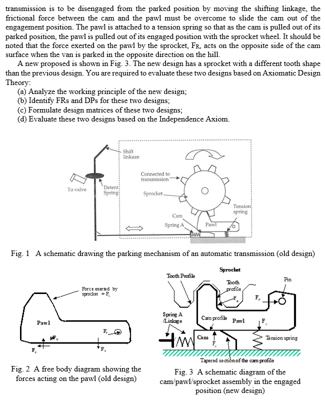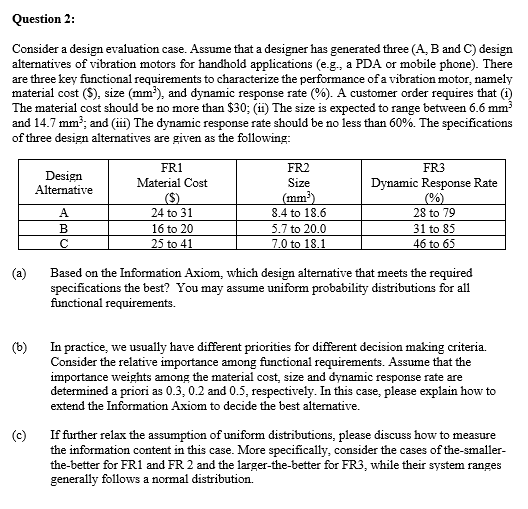


Question 1: Automatic transmission of automobiles has a park mode (i.e., position), which is designed to prevent an unattended parked vehicle from moving on its own. When the gear is in the parking mode, it locks the transmission mechanism. An automobile company has been investigating a new design concept to overcome the shortcomings of current products. Their customers complained that it is difficult to disengage the gear from the parked position when the vehicle is parked on a steep hill. Also there can be an excessive vibration when the gear is removed from the parking position on a steep hill. Their design is shown in Fig. 1. The figure shows the parked position where the pawl is locked into the "sprocket" wheel, which is achieved by means of a shift-linkage mechanism. The sprocket wheel is attached to the transmission. Fig. 2 is a free body diagram of current design, showing the forces acting on the pawl. When the shift linkage is moved to put the car in the parked position, it activates the detent spring and turns the notched cam disk that activates the hydraulic system, etc. The shifting action also pushes the spring (Spring A) that is attached to the cam that supports the load transmitted by the pawl. The surface of the cam is so profiled that when the spring load due to the shifting action is greater than the force resisting the engagement of the pawl with the sprocket wheel, the cam pushes the pawl into the engagement position, locking the sprocket wheel in stationary position. Now the car is in parked position. The pawl cannot accidentally engage with the sprocket wheel while the car is in motion because the impact load between the sprocket and the pawl when the car is moving at more than 3 miles an hour. The tooth profile of the sprocket wheel and the profile of the pawl are so shaped that they cannot be engaged when the impact load between them is larger than the load exerted by Spring A. When the impact load is greater than the spring force, the pawl is kicked back, preventing the pawl from moving into the locked position. When the car is parked on a hill the entire vehicle weight exerts a torque on the sprocket wheel which is transmitted through the teeth and the pawl to the cam. Thus, when the automatic transmission is to be disengaged from the parked position by moving the shifting linkage, the frictional force between the cam and the pawl must be overcome to slide the cam out of the engagement position. The pawl is attached to a tension spring so that as the cam is pulled out of its parked position, the pawl is pulled out of its engaged position with the sprocket wheel. It should be noted that the force exerted on the pawl by the sprocket, FR, acts on the opposite side of the cam surface when the van is parked in the opposite direction on the hill. A new proposed is shown in Fig. 3. The new design has a sprocket with a different tooth shape than the previous design. You are required to evaluate these two designs based on Axiomatic Design Theory: (a) Analyze the working principle of the new design; (6) Identify FRs and DPs for these two designs; (c) Formulate design matrices of these two designs; (d) Evaluate these two designs based on the Independence Axiom. Shift linkage Connected to transmission To valve Detent! Spring Sprocket. Tension spring Cam Spring A Pawl Fig. 1 A schematic drawing the parking mechanism of an automatic transmission (old design) Tooth Profile Sprocket Tooth profile Pin Force exerted by sprocket = F Spring A /Linlage Cam profile Pawl Pawl Cam Tension spring Fig. 2 A free body diagram showing the forces acting on the pawl (old design) Tapered section of the cam profile Fig. 3 A schematic diagram of the cam/pawl/sprocket assembly in the engaged position (new design) Question 2: Consider a design evaluation case. Assume that a designer has generated three (A, B and C) design alternatives of vibration motors for handhold applications (e.g., a PDA or mobile phone). There are three key functional requirements to characterize the performance of a vibration motor, namely material cost (S), size (mm), and dynamic response rate (%). A customer order requires that (1) The material cost should be no more than $30; (11) The size is expected to range between 6.6 mm and 14.7 mm?; and (11) The dynamic response rate should be no less than 60%. The specifications of three design alternatives are given as the following: Design Alternative FR1 Material Cost FR2 Size (mm) 8.4 to 18.6 5.7 to 20.0 7.0 to 18.1 B 24 to 31 16 to 20 25 to 41 FR3 Dynamic Response Rate (%) 28 to 79 31 to 85 46 to 65 Based on the Information Axiom, which design alternative that meets the required specifications the best? You may assume uniform probability distributions for all functional requirements. (6) In practice, we usually have different priorities for different decision making criteria. Consider the relative importance among functional requirements. Assume that the importance weights among the material cost size and dynamic response rate are determined a priori as 0.3, 0.2 and 0.5, respectively. In this case, please explain how to extend the Information Axiom to decide the best alternative. If further relax the assumption of uniform distributions, please discuss how to measure the information content in this case. More specifically, consider the cases of the smaller- the-better for FR1 and FR 2 and the larger-the-better for FR3, while their system ranges generally follows a normal distribution. c) Question 1: Automatic transmission of automobiles has a park mode (i.e., position), which is designed to prevent an unattended parked vehicle from moving on its own. When the gear is in the parking mode, it locks the transmission mechanism. An automobile company has been investigating a new design concept to overcome the shortcomings of current products. Their customers complained that it is difficult to disengage the gear from the parked position when the vehicle is parked on a steep hill. Also there can be an excessive vibration when the gear is removed from the parking position on a steep hill. Their design is shown in Fig. 1. The figure shows the parked position where the pawl is locked into the "sprocket" wheel, which is achieved by means of a shift-linkage mechanism. The sprocket wheel is attached to the transmission. Fig. 2 is a free body diagram of current design, showing the forces acting on the pawl. When the shift linkage is moved to put the car in the parked position, it activates the detent spring and turns the notched cam disk that activates the hydraulic system, etc. The shifting action also pushes the spring (Spring A) that is attached to the cam that supports the load transmitted by the pawl. The surface of the cam is so profiled that when the spring load due to the shifting action is greater than the force resisting the engagement of the pawl with the sprocket wheel, the cam pushes the pawl into the engagement position, locking the sprocket wheel in stationary position. Now the car is in parked position. The pawl cannot accidentally engage with the sprocket wheel while the car is in motion because the impact load between the sprocket and the pawl when the car is moving at more than 3 miles an hour. The tooth profile of the sprocket wheel and the profile of the pawl are so shaped that they cannot be engaged when the impact load between them is larger than the load exerted by Spring A. When the impact load is greater than the spring force, the pawl is kicked back, preventing the pawl from moving into the locked position. When the car is parked on a hill the entire vehicle weight exerts a torque on the sprocket wheel which is transmitted through the teeth and the pawl to the cam. Thus, when the automatic transmission is to be disengaged from the parked position by moving the shifting linkage, the frictional force between the cam and the pawl must be overcome to slide the cam out of the engagement position. The pawl is attached to a tension spring so that as the cam is pulled out of its parked position, the pawl is pulled out of its engaged position with the sprocket wheel. It should be noted that the force exerted on the pawl by the sprocket, FR, acts on the opposite side of the cam surface when the van is parked in the opposite direction on the hill. A new proposed is shown in Fig. 3. The new design has a sprocket with a different tooth shape than the previous design. You are required to evaluate these two designs based on Axiomatic Design Theory: (a) Analyze the working principle of the new design; (6) Identify FRs and DPs for these two designs; (c) Formulate design matrices of these two designs; (d) Evaluate these two designs based on the Independence Axiom. Shift linkage Connected to transmission To valve Detent! Spring Sprocket. Tension spring Cam Spring A Pawl Fig. 1 A schematic drawing the parking mechanism of an automatic transmission (old design) Tooth Profile Sprocket Tooth profile Pin Force exerted by sprocket = F Spring A /Linlage Cam profile Pawl Pawl Cam Tension spring Fig. 2 A free body diagram showing the forces acting on the pawl (old design) Tapered section of the cam profile Fig. 3 A schematic diagram of the cam/pawl/sprocket assembly in the engaged position (new design) Question 2: Consider a design evaluation case. Assume that a designer has generated three (A, B and C) design alternatives of vibration motors for handhold applications (e.g., a PDA or mobile phone). There are three key functional requirements to characterize the performance of a vibration motor, namely material cost (S), size (mm), and dynamic response rate (%). A customer order requires that (1) The material cost should be no more than $30; (11) The size is expected to range between 6.6 mm and 14.7 mm?; and (11) The dynamic response rate should be no less than 60%. The specifications of three design alternatives are given as the following: Design Alternative FR1 Material Cost FR2 Size (mm) 8.4 to 18.6 5.7 to 20.0 7.0 to 18.1 B 24 to 31 16 to 20 25 to 41 FR3 Dynamic Response Rate (%) 28 to 79 31 to 85 46 to 65 Based on the Information Axiom, which design alternative that meets the required specifications the best? You may assume uniform probability distributions for all functional requirements. (6) In practice, we usually have different priorities for different decision making criteria. Consider the relative importance among functional requirements. Assume that the importance weights among the material cost size and dynamic response rate are determined a priori as 0.3, 0.2 and 0.5, respectively. In this case, please explain how to extend the Information Axiom to decide the best alternative. If further relax the assumption of uniform distributions, please discuss how to measure the information content in this case. More specifically, consider the cases of the smaller- the-better for FR1 and FR 2 and the larger-the-better for FR3, while their system ranges generally follows a normal distribution. c)


