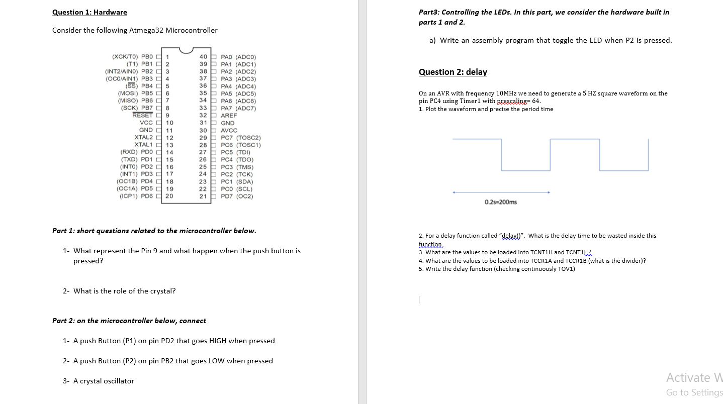
Question: Question 1: Hardware Part3: Controlling the LEDs. In this part, we consider the hardware built in parts 1 and 2. Consider the following Atmega32 Microcontroller

Question 1: Hardware Part3: Controlling the LEDs. In this part, we consider the hardware built in parts 1 and 2. Consider the following Atmega32 Microcontroller a) Write an assembly program that toggle the LED when P2 is pressed. Question 2: delay On an AVR with frequency 10MHz we need to generate a 5 HZ square waveform on the pin PC4 using Timerl with prescaling=64. 1. Plot the waveform and precise the period time (XCK/TO) PBO 1 (T1) PB1 2 (INT2/AINO) PB2 D 3 (OCO/AIN1) PB3 4 (SS) PB4 5 (MOSI) PB5 6 (MISO) PB6 7 (SCK) PB7 0 8 RESET 9 Vcc 10 GND 11 XTAL2 12 XTAL1 13 (RXD) PDO 14 (TXD) PD1 15 (INTO) PD2 16 (INT1) PD3 17 (OC1B) PD4 18 (OC1A) PD5 19 (ICP1) PD6 0 20 40 PAO (ADCO) 39 PA1 (ADC1) 38 PA2 (ADC2) 37 PA3 (ADC3) 36 PA4 (ADC4) 35PA5 (ADC5) 34 PA6 (ADC6) 33 PA7 (ADC7) 32 AREF 31 GND 30 AVCC 29 PC7 (TOSC2) 28PC6 (TOSC1) 27 PC5 (TDI) 26 b PC4 (TDO) 25 PC3 (TMS) 24 PC2 (TCK) 23 PC1 (SDA) 22PCO (SCL) 21 PD7 (OC2) 0.25=200ms Part 1: short questions related to the microcontroller below. 1- What represent the Pin 9 and what happen when the push button is pressed? 2. For a delay function called "delay". What is the delay time to be wasted inside this fuostian 3. What are the values to be loaded into TCNTIH and TCNT1 4. What are the values to be loaded into TCCR1A and TCCR1B (what is the divider)? 5. Write the delay function (checking continuously TOV1) 2- What is the role of the crystal? | Part 2: on the microcontroller below, connect 1- A push Button (P1) on pin PD2 that goes HIGH when pressed 2- A push Button (P2) on pin PB2 that goes LOW when pressed 3- A crystal oscillator Activate v Go to Settings Question 1: Hardware Part3: Controlling the LEDs. In this part, we consider the hardware built in parts 1 and 2. Consider the following Atmega32 Microcontroller a) Write an assembly program that toggle the LED when P2 is pressed. Question 2: delay On an AVR with frequency 10MHz we need to generate a 5 HZ square waveform on the pin PC4 using Timerl with prescaling=64. 1. Plot the waveform and precise the period time (XCK/TO) PBO 1 (T1) PB1 2 (INT2/AINO) PB2 D 3 (OCO/AIN1) PB3 4 (SS) PB4 5 (MOSI) PB5 6 (MISO) PB6 7 (SCK) PB7 0 8 RESET 9 Vcc 10 GND 11 XTAL2 12 XTAL1 13 (RXD) PDO 14 (TXD) PD1 15 (INTO) PD2 16 (INT1) PD3 17 (OC1B) PD4 18 (OC1A) PD5 19 (ICP1) PD6 0 20 40 PAO (ADCO) 39 PA1 (ADC1) 38 PA2 (ADC2) 37 PA3 (ADC3) 36 PA4 (ADC4) 35PA5 (ADC5) 34 PA6 (ADC6) 33 PA7 (ADC7) 32 AREF 31 GND 30 AVCC 29 PC7 (TOSC2) 28PC6 (TOSC1) 27 PC5 (TDI) 26 b PC4 (TDO) 25 PC3 (TMS) 24 PC2 (TCK) 23 PC1 (SDA) 22PCO (SCL) 21 PD7 (OC2) 0.25=200ms Part 1: short questions related to the microcontroller below. 1- What represent the Pin 9 and what happen when the push button is pressed? 2. For a delay function called "delay". What is the delay time to be wasted inside this fuostian 3. What are the values to be loaded into TCNTIH and TCNT1 4. What are the values to be loaded into TCCR1A and TCCR1B (what is the divider)? 5. Write the delay function (checking continuously TOV1) 2- What is the role of the crystal? | Part 2: on the microcontroller below, connect 1- A push Button (P1) on pin PD2 that goes HIGH when pressed 2- A push Button (P2) on pin PB2 that goes LOW when pressed 3- A crystal oscillator Activate v Go to Settings
Step by Step Solution
There are 3 Steps involved in it
Question 1 Hardware Part 1 Short Questions 1 What does Pin 9 represent and what happens when the push button is pressed Pin 9 on the ATmega32 is the R... View full answer

Get step-by-step solutions from verified subject matter experts


