Answered step by step
Verified Expert Solution
Question
1 Approved Answer
Question 1: (Marks 10-CLO2) . . . . . High Level . Sensor Figure 1 The system shown in Figure 1 represents a PLC

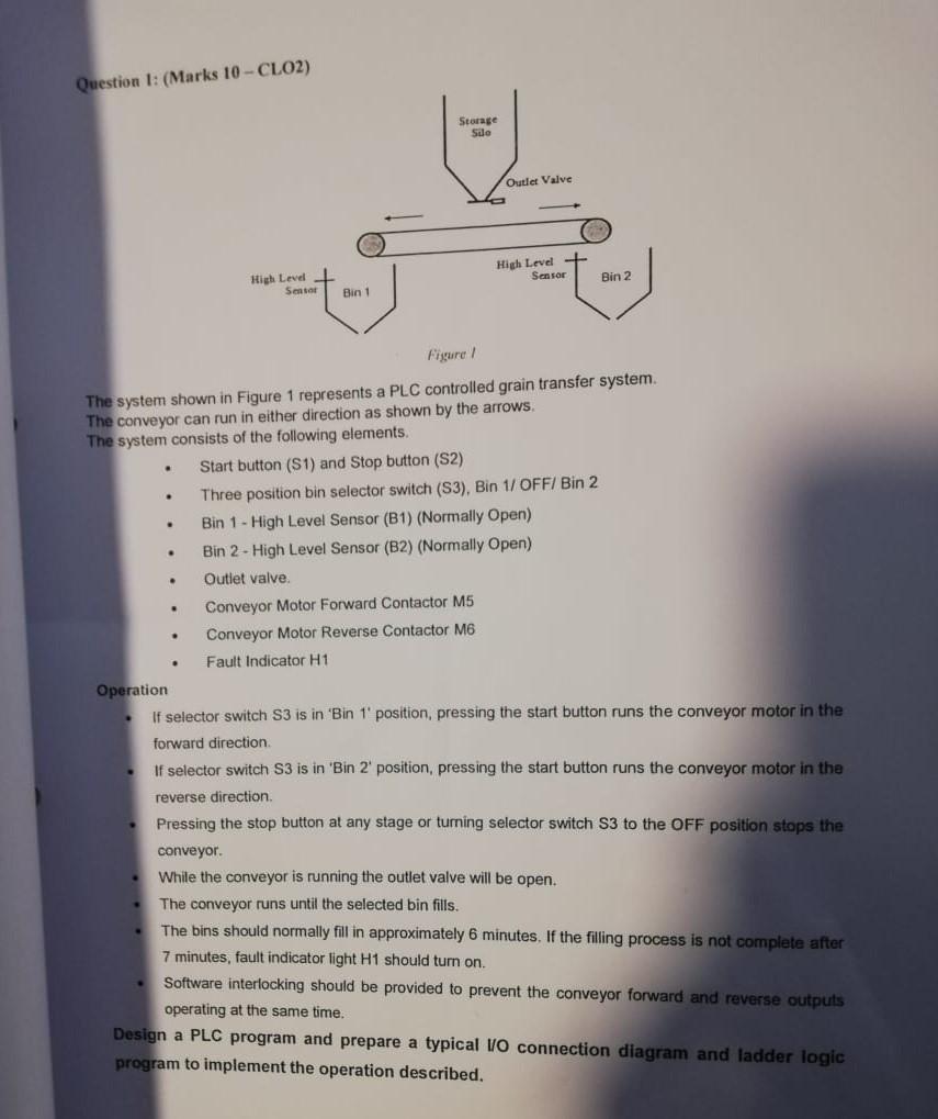
Question 1: (Marks 10-CLO2) . . . . . High Level . Sensor Figure 1 The system shown in Figure 1 represents a PLC controlled grain transfer system. The conveyor can run in either direction as shown by the arrows. The system consists of the following elements. Bin 1 Storage Silo Outlet Valve High Level + Sensor Conveyor Motor Forward Contactor M5 Conveyor Motor Reverse Contactor M6 Fault Indicator H1 Start button (S1) and Stop button (S2) Three position bin selector switch (S3), Bin 1/ OFF/ Bin 2 Bin 1-High Level Sensor (B1) (Normally Open) Bin 2-High Level Sensor (B2) (Normally Open) Outlet valve. Bin 2 Operation If selector switch S3 is in 'Bin 1' position, pressing the start button runs the conveyor motor in the forward direction. If selector switch S3 is in 'Bin 2' position, pressing the start button runs the conveyor motor in the reverse direction. Pressing the stop button at any stage or turning selector switch S3 to the OFF position stops the conveyor. While the conveyor is running the outlet valve will be open. The conveyor runs until the selected bin fills. The bins should normally fill in approximately 6 minutes. If the filling process is not complete after 7 minutes, fault indicator light H1 should turn on. Software interlocking should be provided to prevent the conveyor forward and reverse outputs operating at the same time. Design a PLC program and prepare a typical I/O connection diagram and ladder logic program to implement the operation described.
Step by Step Solution
★★★★★
3.43 Rating (150 Votes )
There are 3 Steps involved in it
Step: 1
This is a control systems question specifically related to a PLC Programmable Logic Controller contr...
Get Instant Access to Expert-Tailored Solutions
See step-by-step solutions with expert insights and AI powered tools for academic success
Step: 2

Step: 3

Ace Your Homework with AI
Get the answers you need in no time with our AI-driven, step-by-step assistance
Get Started


