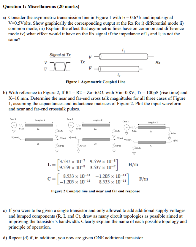
Question 1: Miscellaneous (20 marks) a) Consider the asymmetric transmission line in Figure 1 with 12 = 0.6*l, and input signal V=0.5Volts. Show graphically the corresponding output at the Rx for i) differential mode ii) common mode, iii) Explain the effect that asymmetric lines have on common and difference mode iv) what effect would it have on the Rx signal if the impedance of l; and 12 is not the same? 14 Signal at Tx Tx Rx a vo 12 Figure 1 Asymmetric Coupled Line b) With reference to Figure 2, If R1 = R2 = Zo=6512, with Vin=0.8V, Tr = 100pS (rise time) and X=10 mm. Determine the near and far-end cross talk magnitudes for all three cases of Figure 1, assuming the capacitances and inductance matrices of Figure 2. Plot the input waveform and near and far-end crosstalk pulses. Case 3 Length - X Case 1 Length - X Case 2 Length - X R-Zo Zo R-Zo 20 R-Zo R=20 R-Zo 20 R=20 Vineari Vifar) Vinear Vifar) Minear) Vitar) Zo Zo R2-20 R1-20 R2-20 Zo R1-20 [3.537 x 10⁻⁷ 9.559 x 10 L= H/m (9.559 x 10⁻⁸ 3.537 x 10⁻⁷ 8.533 x 10⁻¹¹ -1.205 x 10-117 CE -1.205 x 10⁻¹¹ 8.533 x 10⁻¹¹ Figure 2 Coupled line and near and far end response F/m c) If you were to be given a single transistor and only allowed to add additional supply voltages and lumped components (R, L and C), draw as many circuit topologies as possible aimed at improving the transistor's bandwidth. Clearly explain the name of each possible topology and principle of operation. d) Repeat (d) if, in addition, you now are given ONE additional transistor. Question 1: Miscellaneous (20 marks) a) Consider the asymmetric transmission line in Figure 1 with 12 = 0.6*l, and input signal V=0.5Volts. Show graphically the corresponding output at the Rx for i) differential mode ii) common mode, iii) Explain the effect that asymmetric lines have on common and difference mode iv) what effect would it have on the Rx signal if the impedance of l; and 12 is not the same? 14 Signal at Tx Tx Rx a vo 12 Figure 1 Asymmetric Coupled Line b) With reference to Figure 2, If R1 = R2 = Zo=6512, with Vin=0.8V, Tr = 100pS (rise time) and X=10 mm. Determine the near and far-end cross talk magnitudes for all three cases of Figure 1, assuming the capacitances and inductance matrices of Figure 2. Plot the input waveform and near and far-end crosstalk pulses. Case 3 Length - X Case 1 Length - X Case 2 Length - X R-Zo Zo R-Zo 20 R-Zo R=20 R-Zo 20 R=20 Vineari Vifar) Vinear Vifar) Minear) Vitar) Zo Zo R2-20 R1-20 R2-20 Zo R1-20 [3.537 x 10⁻⁷ 9.559 x 10 L= H/m (9.559 x 10⁻⁸ 3.537 x 10⁻⁷ 8.533 x 10⁻¹¹ -1.205 x 10-117 CE -1.205 x 10⁻¹¹ 8.533 x 10⁻¹¹ Figure 2 Coupled line and near and far end response F/m c) If you were to be given a single transistor and only allowed to add additional supply voltages and lumped components (R, L and C), draw as many circuit topologies as possible aimed at improving the transistor's bandwidth. Clearly explain the name of each possible topology and principle of operation. d) Repeat (d) if, in addition, you now are given ONE additional transistor