Question
Question 10 [22 marks] A centrifugal pump is configured as shown in Figure 10.1. The pump geometry is defined by r = 350 mm,

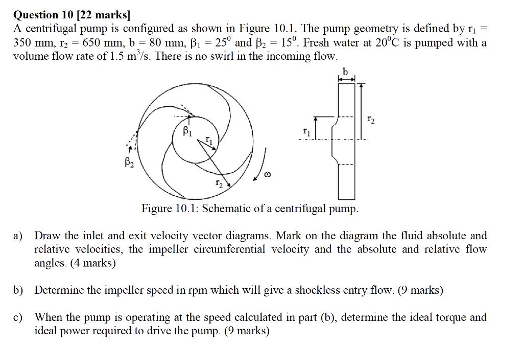
Question 10 [22 marks] A centrifugal pump is configured as shown in Figure 10.1. The pump geometry is defined by r = 350 mm, r = 650 mm, b = 80 mm, = 25 and B = 15. Fresh water at 20C is pumped with a volume flow rate of 1.5 m/s. There is no swirl in the incoming flow. B B 12 Figure 10.1: Schematic of a centrifugal pump. a) Draw the inlet and exit velocity vector diagrams. Mark on the diagram the fluid absolute and relative velocities, the impeller circumferential velocity and the absolute and relative flow angles. (4 marks) b) Determine the impeller speed in rpm which will give a shockless entry flow. (9 marks) c) When the pump is operating at the speed calculated in part (b), determine the ideal torque and ideal power required to drive the pump. (9 marks)
Step by Step Solution
There are 3 Steps involved in it
Step: 1

Get Instant Access to Expert-Tailored Solutions
See step-by-step solutions with expert insights and AI powered tools for academic success
Step: 2

Step: 3

Ace Your Homework with AI
Get the answers you need in no time with our AI-driven, step-by-step assistance
Get StartedRecommended Textbook for
Fundamentals Of Hydraulic Engineering Systems
Authors: Robert J. Houghtalen, A. Osman H. Akan, Ned H. C. Hwang
4th Edition
136016383, 978-0136016380
Students also viewed these Physics questions
Question
Answered: 1 week ago
Question
Answered: 1 week ago
Question
Answered: 1 week ago
Question
Answered: 1 week ago
Question
Answered: 1 week ago
Question
Answered: 1 week ago
Question
Answered: 1 week ago
Question
Answered: 1 week ago
Question
Answered: 1 week ago
Question
Answered: 1 week ago
Question
Answered: 1 week ago
Question
Answered: 1 week ago
Question
Answered: 1 week ago
Question
Answered: 1 week ago
Question
Answered: 1 week ago
Question
Answered: 1 week ago
Question
Answered: 1 week ago
Question
Answered: 1 week ago
Question
Answered: 1 week ago
Question
Answered: 1 week ago
Question
Answered: 1 week ago
Question
Answered: 1 week ago
View Answer in SolutionInn App


