Answered step by step
Verified Expert Solution
Question
1 Approved Answer
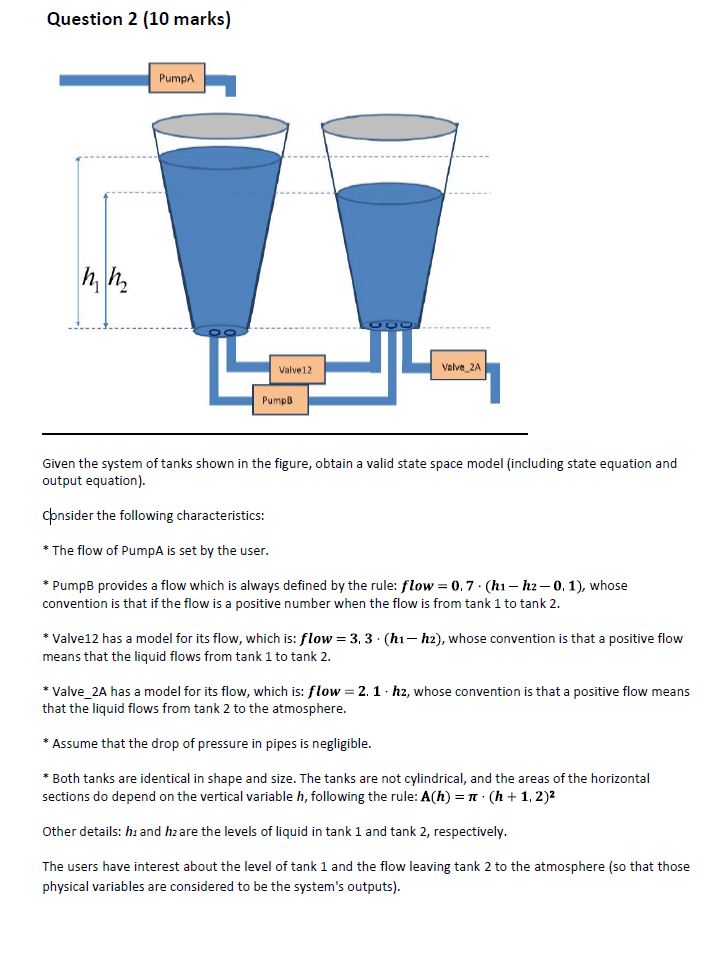
Question 2 (10 marks) hh PumpA Valve 2A Valve 12 PumpB Given the system of tanks shown in the figure, obtain a valid state

Question 2 (10 marks) hh PumpA Valve 2A Valve 12 PumpB Given the system of tanks shown in the figure, obtain a valid state space model (including state equation and output equation). consider the following characteristics: * The flow of PumpA is set by the user. * PumpB provides a flow which is always defined by the rule: flow = 0.7 (hi-h2-0. 1), whose convention is that if the flow is a positive number when the flow is from tank 1 to tank 2. * Valve 12 has a model for its flow, which is: flow = 3.3 (hi-h2), whose convention is that a positive flow means that the liquid flows from tank 1 to tank 2. * Valve_2A has a model for its flow, which is: flow = 2.1 h2, whose convention is that a positive flow means that the liquid flows from tank 2 to the atmosphere. * Assume that the drop of pressure in pipes is negligible. * Both tanks are identical in shape and size. The tanks are not cylindrical, and the areas of the horizontal sections do depend on the vertical variable h, following the rule: A(h) = (h+1, 2) Other details: hi and hz are the levels of liquid in tank 1 and tank 2, respectively. The users have interest about the level of tank 1 and the flow leaving tank 2 to the atmosphere (so that those physical variables are considered to be the system's outputs).
Step by Step Solution
There are 3 Steps involved in it
Step: 1

Get Instant Access to Expert-Tailored Solutions
See step-by-step solutions with expert insights and AI powered tools for academic success
Step: 2

Step: 3

Ace Your Homework with AI
Get the answers you need in no time with our AI-driven, step-by-step assistance
Get Started


