Answered step by step
Verified Expert Solution
Question
1 Approved Answer
Question 2 [30 marks] For this question, imagine you are an independent consultant engaged to review and check the design of a 5m deep


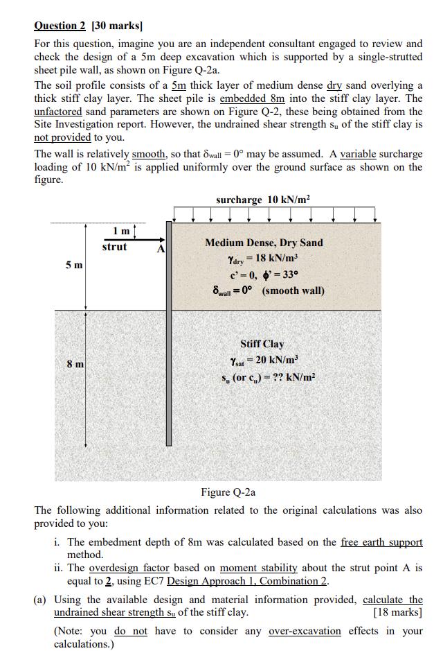
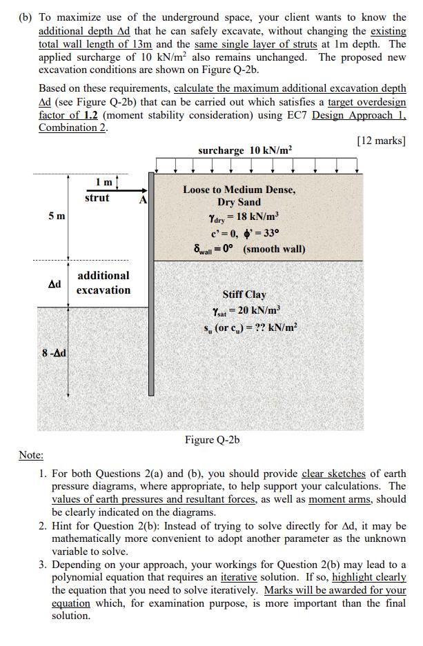
Question 2 [30 marks] For this question, imagine you are an independent consultant engaged to review and check the design of a 5m deep excavation which is supported by a single-strutted sheet pile wall, as shown on Figure Q-2a. The soil profile consists of a 5m thick layer of medium dense dry sand overlying a thick stiff clay layer. The sheet pile is embedded 8m into the stiff clay layer. The unfactored sand parameters are shown on Figure Q-2, these being obtained from the Site Investigation report. However, the undrained shear strength s of the stiff clay is not provided to you. The wall is relatively smooth, so that wall =0 may be assumed. A variable surcharge loading of 10 kN/m is applied uniformly over the ground surface as shown on the figure. 5 m 1 m strut 8 m surcharge 10 kN/m Medium Dense, Dry Sand A Ydry = 18 kN/m c'=0, '=33 = Swall 0 (smooth wall) Stiff Clay Ysat 20 kN/m = s, (or c) ?? kN/m Figure Q-2a The following additional information related to the original calculations was also provided to you: i. The embedment depth of 8m was calculated based on the free earth support method. ii. The overdesign factor based on moment stability about the strut point A is equal to 2, using EC7 Design Approach 1, Combination 2. (a) Using the available design and material information provided, calculate the undrained shear strength s of the stiff clay. [18 marks] (Note: you do not have to consider any over-excavation effects in your calculations.) (b) To maximize use of the underground space, your client wants to know the additional depth Ad that he can safely excavate, without changing the existing total wall length of 13m and the same single layer of struts at Im depth. The applied surcharge of 10 kN/m also remains unchanged. The proposed new excavation conditions are shown on Figure Q-2b. Based on these requirements, calculate the maximum additional excavation depth Ad (see Figure Q-2b) that can be carried out which satisfies a target overdesign factor of 1.2 (moment stability consideration) using EC7 Design Approach 1. Combination 2. surcharge 10 kN/m [12 marks] 1 m strut 5 m Ad additional excavation 8-Ad A Loose to Medium Dense, Dry Sand Ydry 18 kN/m c' 0, '=33 = Swall 0 (smooth wall) Stiff Clay Ysat 20 kN/m = s, (or c)=?? kN/m Note: Figure Q-2b 1. For both Questions 2(a) and (b), you should provide clear sketches of earth pressure diagrams, where appropriate, to help support your calculations. The values of earth pressures and resultant forces, as well as moment arms, should be clearly indicated on the diagrams. 2. Hint for Question 2(b): Instead of trying to solve directly for Ad, it may be mathematically more convenient to adopt another parameter as the unknown variable to solve. 3. Depending on your approach, your workings for Question 2(b) may lead to a polynomial equation that requires an iterative solution. If so, highlight clearly the equation that you need to solve iteratively. Marks will be awarded for your equation which, for examination purpose, is more important than the final solution.
Step by Step Solution
There are 3 Steps involved in it
Step: 1

Get Instant Access to Expert-Tailored Solutions
See step-by-step solutions with expert insights and AI powered tools for academic success
Step: 2

Step: 3

Ace Your Homework with AI
Get the answers you need in no time with our AI-driven, step-by-step assistance
Get Started


