
Question 2:

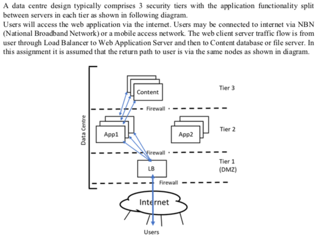
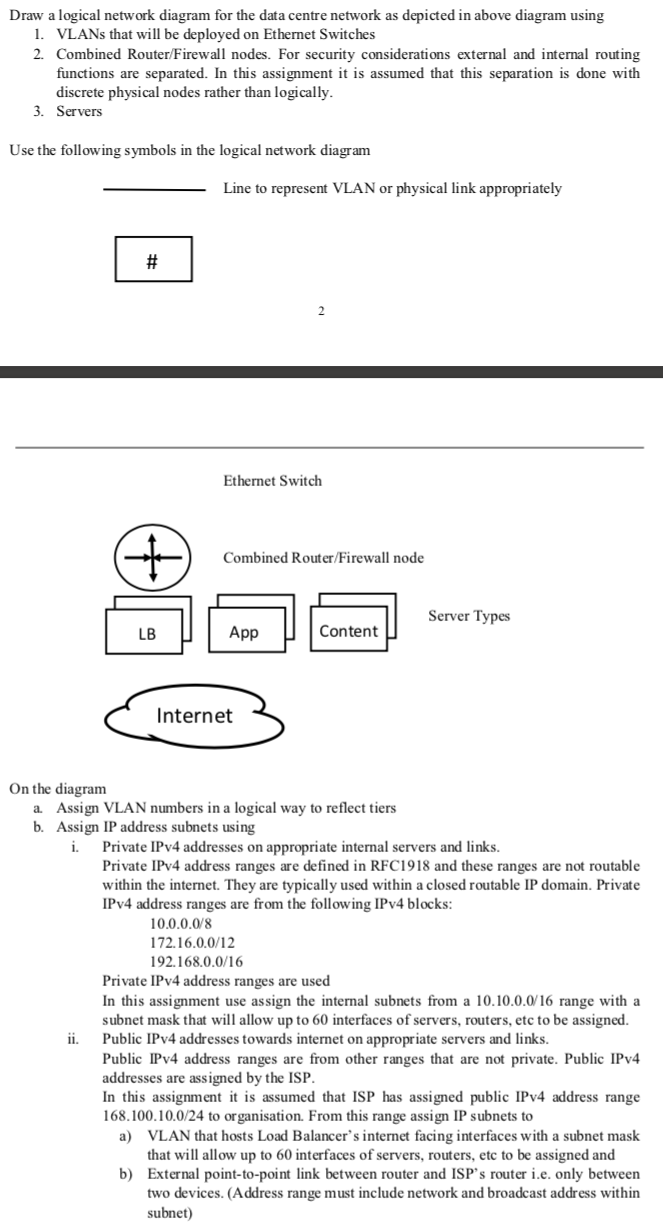
A data centre design typically comprises 3 security tiers with the application functionality split between servers in each tier as shown in following diagram. Users will access the web application via the internet. Users may be connected to internet via NBN (National Broadband Network) or a mobile access network. The web client server traffic flow is from user through Load Balancer to Web Application Server and then to Content database or file server. In this assignment it is assumed that the return path to user is via the same nodes as shown in diagram. Tier 3 Content - Firewall .- Data Centre Tier 2 App1 App2 Firewall. - - - - LB Tier 1 (DMZ) Firewall - - - - Internet Users In this network design VLANs (Virtual Local Area Network) will be used on ethernet switch nodes and connected to combined router/firewall nodes. As shown in the diagram the web application deployment comprises: 1. Load Balancers 2. Web Application Servers 3. Web Content Database or File Servers While user traffic load varies with time of day, the network design needs to support traffic load at peak time of day. At peak traffic time of day, it is assumed that 1. Each user makes 1 web request per minute (i.e. an average per user request rate of 0.0167 requests per second) and that each request comprises 80 KBytes of data. User requests are assumed to be uniformly distributed. 2. Web servers are able to handle 15 requests per second. 3. Web server sends 1.0 MByte of data (including http protocol overhead) in response to each user request and that Web Content Server likewise responds with 1.0 MByte (including protocol overhead) to Web Application Server. Draw a logical network diagram for the data centre network as depicted in above diagram using 1. VLANs that will be deployed on Ethernet Switches 2. Combined Router/Firewall nodes. For security considerations external and internal routing functions are separated. In this assignment it is assumed that this separation is done with discrete physical nodes rather than logically. 3. Servers Use the following symbols in the logical network diagram Line to represent VLAN or physical link appropriately # Ethernet Switch Combined Router/Firewall node Server Types App Content Internet On the diagram a. Assign VLAN numbers in a logical way to reflect tiers b. Assign IP address subnets using i. Private IPv4 addresses on appropriate internal servers and links. Private IPv4 address ranges are defined in RFC1918 and these ranges are not routable within the internet. They are typically used within a closed routable IP domain. Private IPv4 address ranges are from the following IPv4 blocks: 10.0.0.0/8 172.16.0.0/12 192.168.0.0/16 Private IPv4 address ranges are used In this assignment use assign the internal subnets from a 10.10.0.0/16 range with a subnet mask that will allow up to 60 interfaces of servers, routers, etc to be assigned. Public IPv4 addresses towards internet on appropriate servers and links. Public IPv4 address ranges are from other ranges that are not private. Public IPv4 addresses are assigned by the ISP. In this assignment it is assumed that ISP has assigned public IPv4 address range 168.100.10.0/24 to organisation. From this range assign IP subnets to a) VLAN that hosts Load Balancer's internet facing interfaces with a subnet mask that will allow up to 60 interfaces of servers, routers, etc to be assigned and b) External point-to-point link between router and ISP's router i.e. only between two devices. (Address range must include network and broadcast address within subnet) A data centre design typically comprises 3 security tiers with the application functionality split between servers in each tier as shown in following diagram. Users will access the web application via the internet. Users may be connected to internet via NBN (National Broadband Network) or a mobile access network. The web client server traffic flow is from user through Load Balancer to Web Application Server and then to Content database or file server. In this assignment it is assumed that the return path to user is via the same nodes as shown in diagram. Tier 3 Content - Firewall .- Data Centre Tier 2 App1 App2 Firewall. - - - - LB Tier 1 (DMZ) Firewall - - - - Internet Users In this network design VLANs (Virtual Local Area Network) will be used on ethernet switch nodes and connected to combined router/firewall nodes. As shown in the diagram the web application deployment comprises: 1. Load Balancers 2. Web Application Servers 3. Web Content Database or File Servers While user traffic load varies with time of day, the network design needs to support traffic load at peak time of day. At peak traffic time of day, it is assumed that 1. Each user makes 1 web request per minute (i.e. an average per user request rate of 0.0167 requests per second) and that each request comprises 80 KBytes of data. User requests are assumed to be uniformly distributed. 2. Web servers are able to handle 15 requests per second. 3. Web server sends 1.0 MByte of data (including http protocol overhead) in response to each user request and that Web Content Server likewise responds with 1.0 MByte (including protocol overhead) to Web Application Server. Draw a logical network diagram for the data centre network as depicted in above diagram using 1. VLANs that will be deployed on Ethernet Switches 2. Combined Router/Firewall nodes. For security considerations external and internal routing functions are separated. In this assignment it is assumed that this separation is done with discrete physical nodes rather than logically. 3. Servers Use the following symbols in the logical network diagram Line to represent VLAN or physical link appropriately # Ethernet Switch Combined Router/Firewall node Server Types App Content Internet On the diagram a. Assign VLAN numbers in a logical way to reflect tiers b. Assign IP address subnets using i. Private IPv4 addresses on appropriate internal servers and links. Private IPv4 address ranges are defined in RFC1918 and these ranges are not routable within the internet. They are typically used within a closed routable IP domain. Private IPv4 address ranges are from the following IPv4 blocks: 10.0.0.0/8 172.16.0.0/12 192.168.0.0/16 Private IPv4 address ranges are used In this assignment use assign the internal subnets from a 10.10.0.0/16 range with a subnet mask that will allow up to 60 interfaces of servers, routers, etc to be assigned. Public IPv4 addresses towards internet on appropriate servers and links. Public IPv4 address ranges are from other ranges that are not private. Public IPv4 addresses are assigned by the ISP. In this assignment it is assumed that ISP has assigned public IPv4 address range 168.100.10.0/24 to organisation. From this range assign IP subnets to a) VLAN that hosts Load Balancer's internet facing interfaces with a subnet mask that will allow up to 60 interfaces of servers, routers, etc to be assigned and b) External point-to-point link between router and ISP's router i.e. only between two devices. (Address range must include network and broadcast address within subnet)


