Answered step by step
Verified Expert Solution
Question
1 Approved Answer
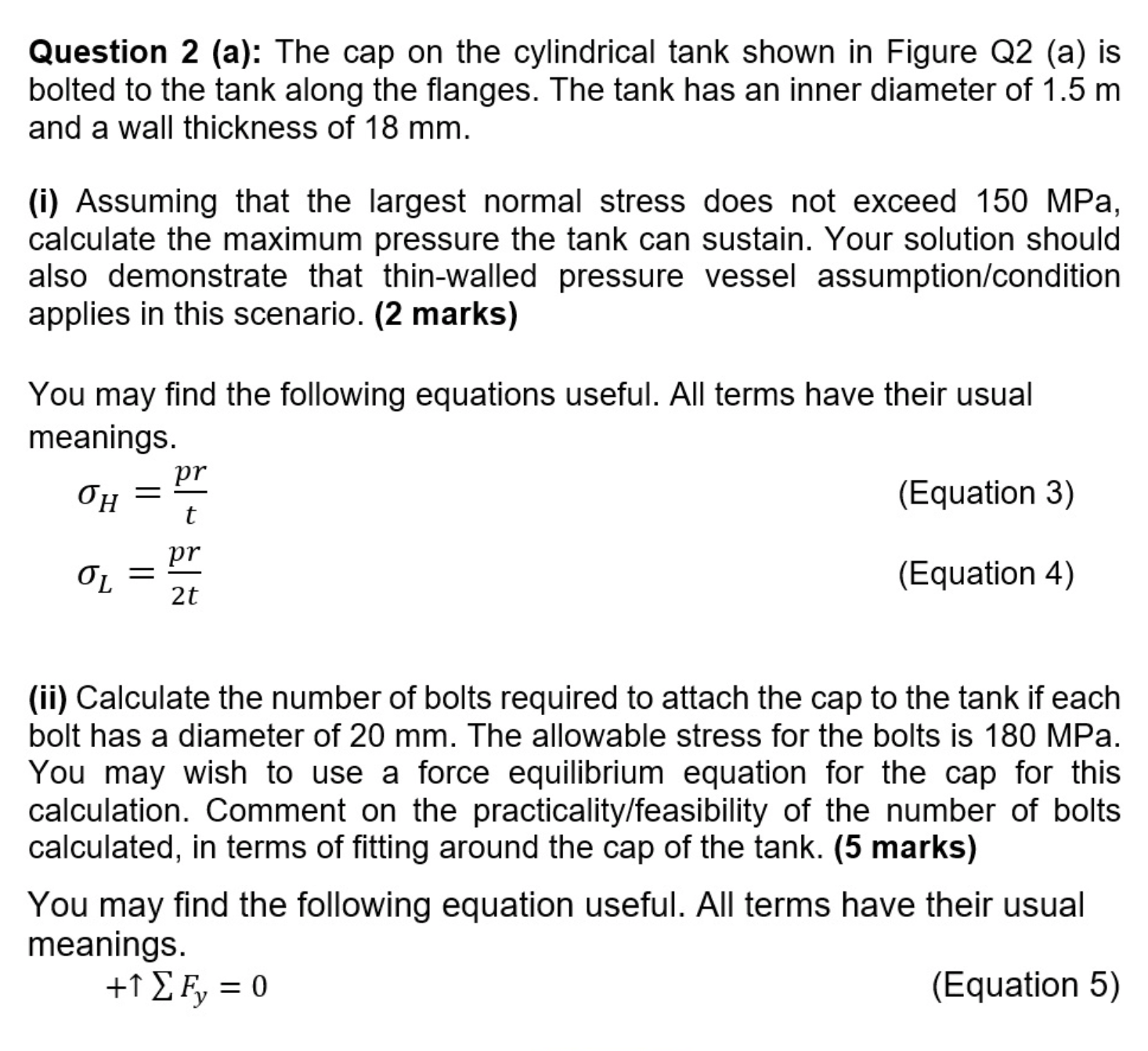
Question 2 (a): The cap on the cylindrical tank shown in Figure Q2 (a) is bolted to the tank along the flanges. The tank

Question 2 (a): The cap on the cylindrical tank shown in Figure Q2 (a) is bolted to the tank along the flanges. The tank has an inner diameter of 1.5 m and a wall thickness of 18 mm. (i) Assuming that the largest normal stress does not exceed 150 MPa, calculate the maximum pressure the tank can sustain. Your solution should also demonstrate that thin-walled pressure vessel assumption/condition applies in this scenario. (2 marks) You may find the following equations useful. All terms have their usual meanings. H = = pr t pr 2t (Equation 3) (Equation 4) (ii) Calculate the number of bolts required to attach the cap to the tank if each bolt has a diameter of 20 mm. The allowable stress for the bolts is 180 MPa. You may wish to use a force equilibrium equation for the cap for this calculation. Comment on the practicality/feasibility of the number of bolts calculated, in terms of fitting around the cap of the tank. (5 marks) You may find the following equation useful. All terms have their usual meanings. +1 , = 0 (Equation 5)
Step by Step Solution
There are 3 Steps involved in it
Step: 1

Get Instant Access to Expert-Tailored Solutions
See step-by-step solutions with expert insights and AI powered tools for academic success
Step: 2

Step: 3

Ace Your Homework with AI
Get the answers you need in no time with our AI-driven, step-by-step assistance
Get Started


