Answered step by step
Verified Expert Solution
Question
1 Approved Answer
Question 2 Figure 2 is a power diode with switched RLC circuit, Figure 3 is a power diode with switched LC Cirauit and Figure 4
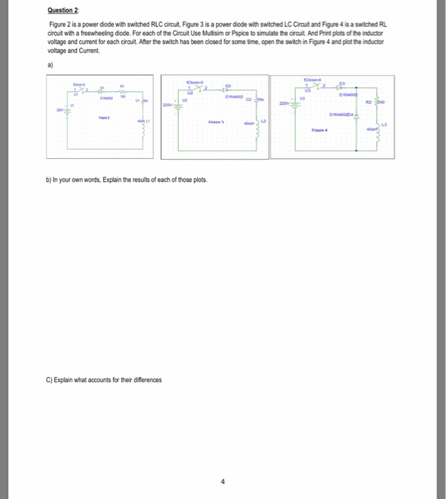
Question 2 Figure 2 is a power diode with switched RLC circuit, Figure 3 is a power diode with switched LC Cirauit and Figure 4 is a switched RL circuit with a freewheeling diode. For each of the Circuit Use Multisim or Pspice to simulate the cirouit. And Print plots of the inductor voltage and current for each circuit. After the switch has been closed for some time, open the switch in Figure 4 and plot the inductor voltage and Current. a) CHS ea 0 ,' b) In your own words, Explain the results of each of those plots. C) Explain what accounts for their differences Question 2 Figure 2 is a power diode with switched RLC circuit, Figure 3 is a power diode with switched LC Cirauit and Figure 4 is a switched RL circuit with a freewheeling diode. For each of the Circuit Use Multisim or Pspice to simulate the cirouit. And Print plots of the inductor voltage and current for each circuit. After the switch has been closed for some time, open the switch in Figure 4 and plot the inductor voltage and Current. a) CHS ea 0 ,' b) In your own words, Explain the results of each of those plots. C) Explain what accounts for their differences
Step by Step Solution
There are 3 Steps involved in it
Step: 1
Get Instant Access to Expert-Tailored Solutions
See step-by-step solutions with expert insights and AI powered tools for academic success
Step: 2
Step: 3
Ace Your Homework with AI
Get the answers you need in no time with our AI-driven, step-by-step assistance
Get Started