Question: The following table is a partial parts list for a gate valve: Part Name Part No. Material Size(inches) Make or Buy Body Bushing 001


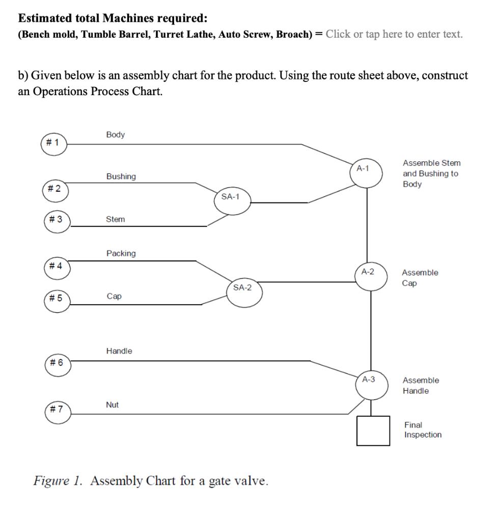
The following table is a partial parts list for a gate valve: Part Name Part No. Material Size(inches) Make or Buy Body Bushing 001 Cast bronze 2.75 x 2.5 x 1.5 Make 2.97 0.87 0.9 x 2.1 002 Cast bronze Make Stem 003 3/8 in. bar stock Make Fiber Packing 004 Sillicon 2.78 x 2.5 x 1.5 Buy Make 005 3/4 in. hex bar stock 1.8 x 0.9 0.42 x 1.20 0.21 x 1.00 Handle 006 Cast bronze Make Nut 007 Aluminum Buy The following is a set of route sheets for a subset of these parts. Operation No. Standard Time Part No. Operations Machine (min/part) 3.00 001-1 Cast Bench mold 001 001-2 Clean Tumble barrel 0.60 001-3 Machine thread Turret lathe 2.40 002-1 Cast Bench mold 0.60 002 002-2 Clean Tumble barrel 0.30 Machine thread Machine all surfaces and cut-off 002-3 Turret lathe 1.50 Automatic Screw Machine 003 003-1 0.30 Automatic 005 005-1 Drill 0.15 Screw Machine 006-1 Cast Bench mold 1.50 006 006-2 Clean Tumble barrel 0.30 006-3 Broach square hole Broach 1.20 a) One unit of each part is required to make the final product. Suppose we want to produce 500 units per hour and assume the machines are effectively 85% reliable. Fill in the table and develop a rough estimate for the number of each type of machine that will be required. Production achines Op.No. t(hours) Machine NM= rate Req 1-1 1-2 1-3 2-1 2-2 2-3 3-1 5-1 6-1 6-2 6-3 Estimated total Machines required: (Bench mold, Tumble Barrel, Turret Lathe, Auto Screw, Broach) = Click or tap here to enter text. b) Given below is an assembly chart for the product. Using the route sheet above, construct an Operations Process Chart. Body # 1 Assemble Stem -1 and Bushing to Body Bushing # 2 SA-1 Stem Packing # 4 A-2 Assemble SA-2 # 5 Handle # 6 -3 Assemble Handle Nut # 7 Final Inspection Figure 1. Assembly Chart for a gate valve.
Step by Step Solution
3.18 Rating (157 Votes )
There are 3 Steps involved in it

Get step-by-step solutions from verified subject matter experts


