Question
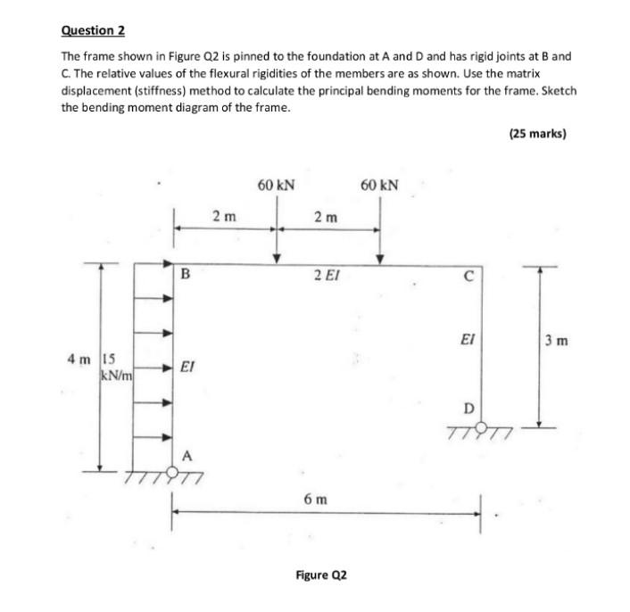
Question 2 The frame shown in Figure Q2 is pinned to the foundation at A and D and has rigid joints at B and

Question 2 The frame shown in Figure Q2 is pinned to the foundation at A and D and has rigid joints at B and C. The relative values of the flexural rigidities of the members are as shown. Use the matrix displacement (stiffness) method to calculate the principal bending moments for the frame. Sketch the bending moment diagram of the frame. 4 m 15 kN/m B 2 m 60 kN 2 m 60 kN 2 El C 6 m Figure Q2 (25 marks) 3 m D 77977
Step by Step Solution
There are 3 Steps involved in it
Step: 1

Get Instant Access to Expert-Tailored Solutions
See step-by-step solutions with expert insights and AI powered tools for academic success
Step: 2

Step: 3

Ace Your Homework with AI
Get the answers you need in no time with our AI-driven, step-by-step assistance
Get StartedRecommended Textbook for
Mechanics of Materials
Authors: James M. Gere, Barry J. Goodno
7th edition
495438073, 978-0495438076
Students also viewed these Civil Engineering questions
Question
Answered: 1 week ago
Question
Answered: 1 week ago
Question
Answered: 1 week ago
Question
Answered: 1 week ago
Question
Answered: 1 week ago
Question
Answered: 1 week ago
Question
Answered: 1 week ago
Question
Answered: 1 week ago
Question
Answered: 1 week ago
Question
Answered: 1 week ago
Question
Answered: 1 week ago
Question
Answered: 1 week ago
Question
Answered: 1 week ago
Question
Answered: 1 week ago
Question
Answered: 1 week ago
Question
Answered: 1 week ago
Question
Answered: 1 week ago
Question
Answered: 1 week ago
Question
Answered: 1 week ago
Question
Answered: 1 week ago
Question
Answered: 1 week ago
Question
Answered: 1 week ago
View Answer in SolutionInn App


