Answered step by step
Verified Expert Solution
Question
1 Approved Answer
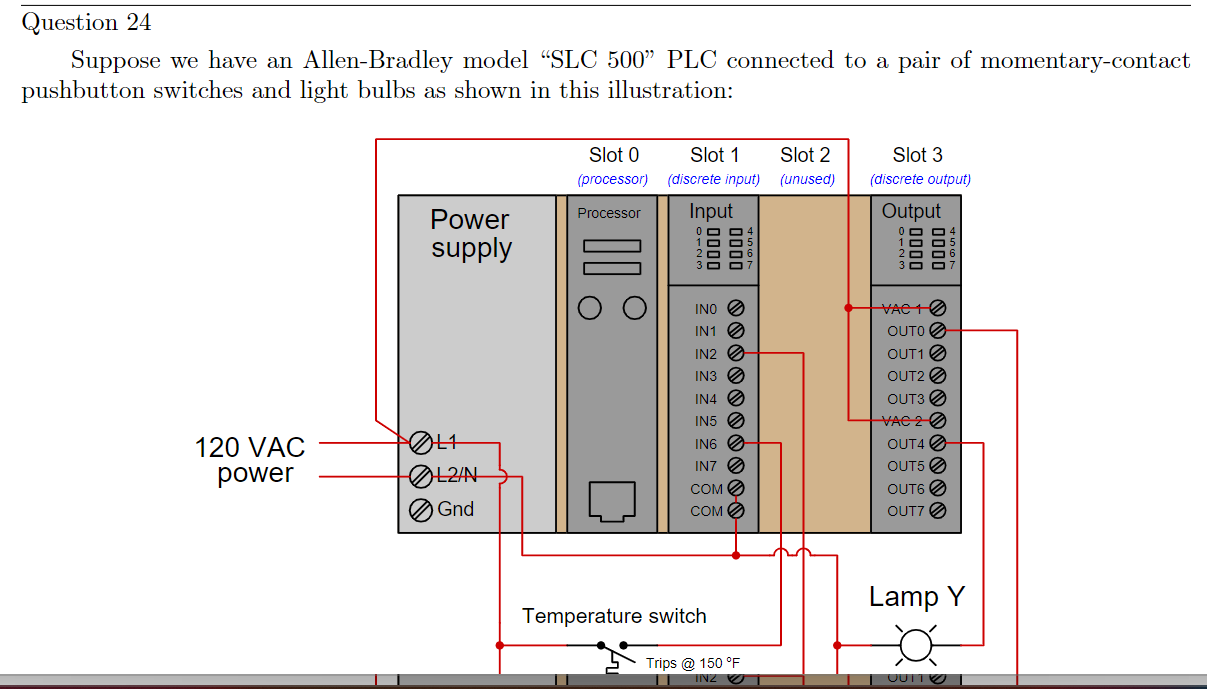
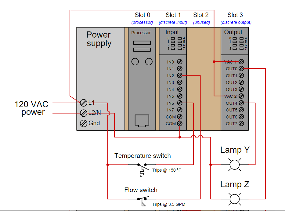
Question 24 Suppose we have an Allen-Bradley model SLC 500 PLC connected to a pair of momentary-contact pushbutton switches and light bulbs as shown


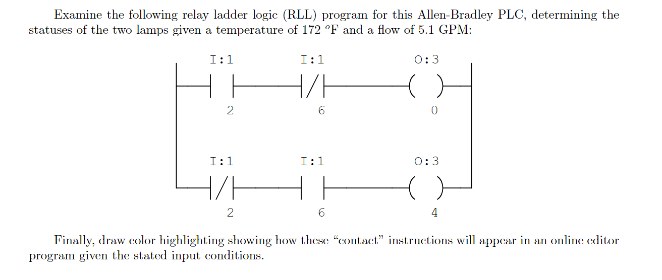
Question 24 Suppose we have an Allen-Bradley model SLC 500 PLC connected to a pair of momentary-contact pushbutton switches and light bulbs as shown in this illustration: Slot 0 (processor) Slot 1 (discrete input) Slot 2 (unused) Slot 3 (discrete output) Power supply Processor Input Output 0000 0000 -0000 0000 4567 120 VAC power L2/N Gnd INO VAC 1 IN1 OUTO IN2 OUT1 IN3 OUT2 IN4 OUT3 IN5 VAC 20 IN6 OUT4 IN7 OUT5 COM OUT6 COM OUT7 Temperature switch Trips @ 150 F IN2 Lamp Y JUTTO Slot 3 (discrete output) Output Power supply Slot 0 (processor) Processor Slot 2 Slot 1 (discrete input) (unused) Input 0723 0000 0000 4557 4557 0000 0000 0723 IN2 IN3 INO IN10 VAC 10 OUTO OUT10 OUT20 IN4 OUT3 IN5 VAC 20 120 VAC power IN6 OUT4 L2/N IN7 OUT50 COM OUT60 Gnd COM OUT70 Temperature switch Trips @ 150 F Flow switch Trips @ 3.5 GPM Lamp Y Lamp Z Cuka Examine the following relay ladder logic (RLL) program for this Allen-Bradley PLC, determining the statuses of the two lamps given a temperature of 172 F and a flow of 5.1 GPM: I: 1 2 I:1 H/H 0:3 6 0 I: 1 I:1 0:3 H/H 2 6 4 Finally, draw color highlighting showing how these "contact" instructions will appear in an online editor program given the stated input conditions.
Step by Step Solution
There are 3 Steps involved in it
Step: 1

Get Instant Access to Expert-Tailored Solutions
See step-by-step solutions with expert insights and AI powered tools for academic success
Step: 2

Step: 3

Ace Your Homework with AI
Get the answers you need in no time with our AI-driven, step-by-step assistance
Get Started


