

Question: Question 3 1 5 marks A simplified model of the single - speed transmission of a lathe is shown in Figure 4 . The transmission
Question
marks
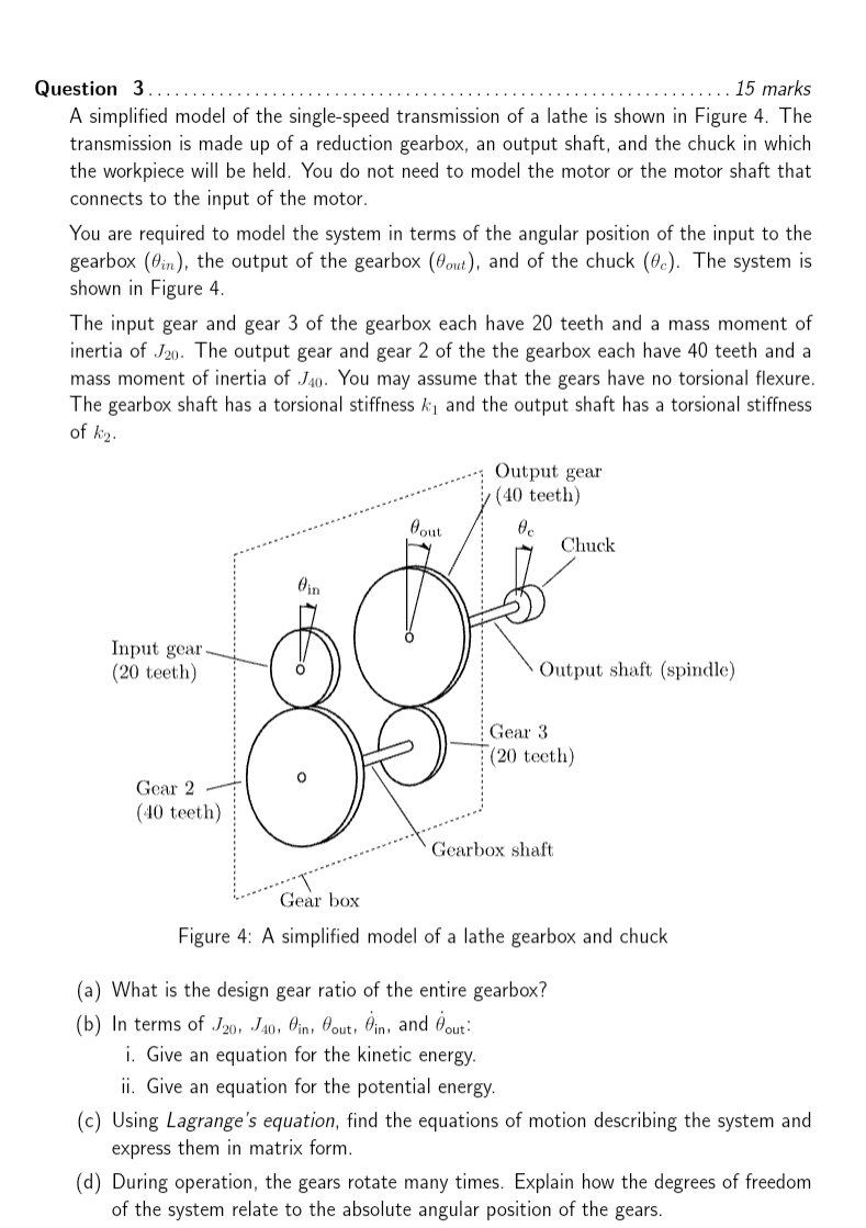
A simplified model of the singlespeed transmission of a lathe is shown in Figure The transmission is made up of a reduction gearbox, an output shaft, and the chuck in which the workpiece will be held. You do not need to model the motor or the motor shaft that connects to the input of the motor.
You are required to model the system in terms of the angular position of the input to the gearbox the output of the gearbox and of the chuck The system is shown in Figure
The input gear and gear of the gearbox each have teeth and a mass moment of inertia of The output gear and gear of the the gearbox each have teeth and a mass moment of inertia of You may assume that the gears have no torsional flexure. The gearbox shaft has a torsional stiffness and the output shaft has a torsional stiffness of
Figure : A simplified model of a lathe gearbox and chuck
a What is the design gear ratio of the entire gearbox?
b In terms of and :
i Give an equation for the kinetic energy.
ii Give an equation for the potential energy.
c Using Lagrange's equation, find the equations of motion describing the system and express them in matrix form.
d During operation, the gears rotate many times. Explain how the degrees of freedom of the system relate to the absolute angular position of the gears.
Step by Step Solution
There are 3 Steps involved in it
1 Expert Approved Answer
Step: 1 Unlock

Question Has Been Solved by an Expert!
Get step-by-step solutions from verified subject matter experts
Step: 2 Unlock
Step: 3 Unlock