Answered step by step
Verified Expert Solution
Question
1 Approved Answer
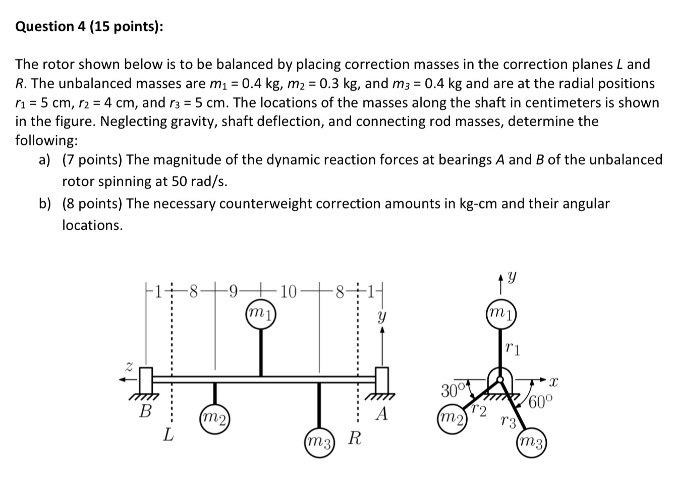
Question 4 (15 points): The rotor shown below is to be balanced by placing correction masses in the correction planes L and R. The

Question 4 (15 points): The rotor shown below is to be balanced by placing correction masses in the correction planes L and R. The unbalanced masses are m = 0.4 kg, m2 = 0.3 kg, and m3 = 0.4 kg and are at the radial positions r = 5 cm, r24 cm, and r3 = 5 cm. The locations of the masses along the shaft in centimeters is shown in the figure. Neglecting gravity, shaft deflection, and connecting rod masses, determine the following: a) (7 points) The magnitude of the dynamic reaction forces at bearings A and B of the unbalanced rotor spinning at 50 rad/s. b) (8 points) The necessary counterweight correction amounts in kg-cm and their angular locations. 18 -9. 10. (m1) M1 r1 x 30 60 r2 B A (m2) r3 (m2) L (m3) R m3
Step by Step Solution
There are 3 Steps involved in it
Step: 1

Get Instant Access to Expert-Tailored Solutions
See step-by-step solutions with expert insights and AI powered tools for academic success
Step: 2

Step: 3

Ace Your Homework with AI
Get the answers you need in no time with our AI-driven, step-by-step assistance
Get Started


