Answered step by step
Verified Expert Solution
Link Copied!

Question

1 Approved Answer

Question 4 (8 marks) Draw an arrow on the coil in Figure 3b to show the direction of the induced current in the Figure 3a
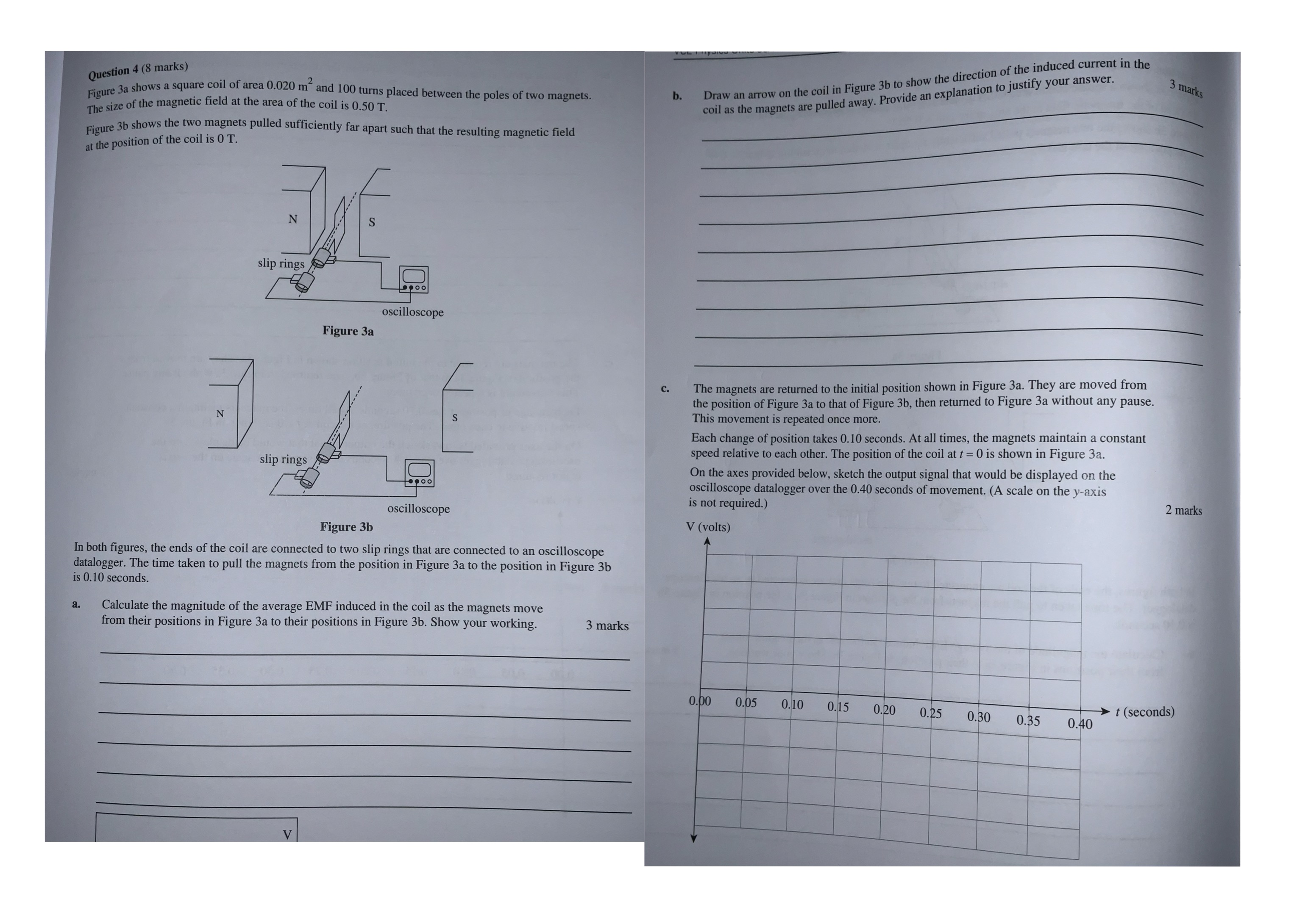
image text in transcribed
Question 4 (8 marks) Draw an arrow on the coil in Figure 3b to show the direction of the induced current in the Figure 3a shows a square coil of area 0.020 m" and 100 turns placed between the poles of two magnets. 3 marks b. coil as the magnets are pulled away. Provide an explanation to justify your answer. The size of the magnetic field at the area of the coil is 0.50 T. Figure 3b shows the two magnets pulled sufficiently far apart such that the resulting magnetic field at the position of the coil is O T. N S slip rings oscilloscope Figure 3a C. The magnets are returned to the initial position shown in Figure 3a. They are moved from the position of Figure 3a to that of Figure 3b, then returned to Figure 3a without any pause. N This movement is repeated once more. Each change of position takes 0.10 seconds. At all times, the magnets maintain a constant speed relative to each other. The position of the coil at t = 0 is shown in Figure 3a. slip rings On the axes provided below, sketch the output signal that would be displayed on the oscilloscope datalogger over the 0.40 seconds of movement. (A scale on the y-axis is not required.) oscilloscope 2 marks Figure 3b V (volts) In both figures, the ends of the coil are connected to two slip rings that are connected to an oscilloscope datalogger. The time taken to pull the magnets from the position in Figure 3a to the position in Figure 3b is 0.10 seconds. a. Calculate the magnitude of the average EMF induced in the coil as the magnets move from their positions in Figure 3a to their positions in Figure 3b. Show your working. 3 marks 0.00 0.05 0.10 0.15 0.20 0.25 0.30 0.35 t (seconds) 0.40

Step by Step Solution

There are 3 Steps involved in it

Step: 1

blur-text-image

Get Instant Access to Expert-Tailored Solutions

See step-by-step solutions with expert insights and AI powered tools for academic success

Step: 2

blur-text-image

Step: 3

blur-text-image

Ace Your Homework with AI

Get the answers you need in no time with our AI-driven, step-by-step assistance

Get Started

Recommended Textbook for

Ferroelectric Devices

Authors: Kenji Uchino

2nd Edition

1351834274, 9781351834278

More Books

Students also viewed these Physics questions

Question

1. The sum of the dice is odd. 2. The sum of the dice is at most 5.

Answered: 1 week ago