Answered step by step
Verified Expert Solution
Link Copied!

Question

1 Approved Answer

Question 4 The block diagram of a feedback control system shown in Figure 2 has been suggested to control a system modelled by a first
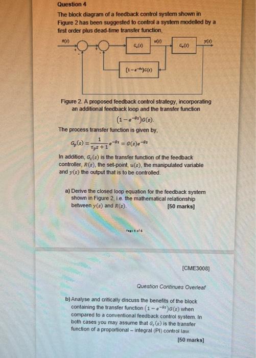
image text in transcribed
Question 4 The block diagram of a feedback control system shown in Figure 2 has been suggested to control a system modelled by a first order plus dead-fime transfer function, Figure 2. A proposed feedback control strategy, incorporating an additional feedback loop and the transfer function (1ex)G(s). The process transfer function is given by, ap(s)=ps+11ex=G(s)ez In addition, Gc(a) is the fransfer function of the feedback controller, R(s), the set-point, u(s), the manipulated variable and y(s) the output that is to be controlled. a) Derive the closed loop equation for the feedback system shown in Figure 2, i.e. the mathematical relationship between y(s) and R(s). [50 marks] [CME3008] Question Continues Overleaf b) Analyse and critically discuss the benefits of the block containing the transfer function (1ets)a(s) when compared to a conventional feedback control system. In both cases you may assume that Gc(s) is the transfer function of a proportional - integral (PI) control law. [50 marks]

Step by Step Solution

There are 3 Steps involved in it

Step: 1

blur-text-image

Get Instant Access to Expert-Tailored Solutions

See step-by-step solutions with expert insights and AI powered tools for academic success

Step: 2

blur-text-image

Step: 3

blur-text-image

Ace Your Homework with AI

Get the answers you need in no time with our AI-driven, step-by-step assistance

Get Started

Recommended Textbook for

Fundamentals Of Thermal-Fluid Sciences

Authors: Yunus Cengel, John Cimbala, Afshin Ghajar

6th Edition

126071697X, 978-1260716979

More Books

Students also viewed these Chemical Engineering questions