Answered step by step
Verified Expert Solution
Question
1 Approved Answer
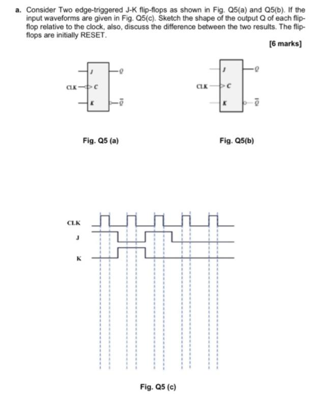
? a. Consider Two edge-triggered J-K flip-flops as shown in Fig. Q5(a) and Q5(b). If the input waveforms are given in Fig. Q5(c). Sketch the
 ?
?


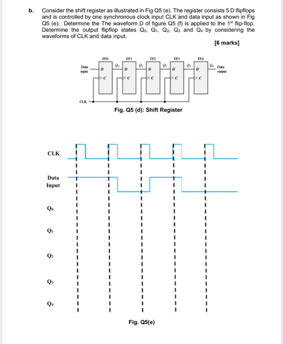
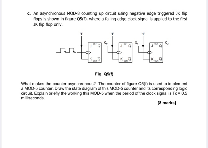
a. Consider Two edge-triggered J-K flip-flops as shown in Fig. Q5(a) and Q5(b). If the input waveforms are given in Fig. Q5(c). Sketch the shape of the output Q of each flip- flop relative to the clock, also, discuss the difference between the two results. The flip- flops are initially RESET. [6 marks] CLK CLK K Fig. Q5 (a) Fig. Q5 (c) CLK Fig. Q5(b) b. Consider the shift register as illustrated in Fig Q5 (e). The register consists 5 D flipflops and is controlled by one synchronous clock input CLK and data input as shown in Fig Q5 (e). Determine the The waveform D of figure Q5 (f) is applied to the 1st flip-flop. Determine the output flipflop states Qo, Q, Q2, Q3 and Q4 by considering the waveforms of CLK and data input. [6 marks] CLK Data Input Q4 input CLK FFO Do FFI D 9 FF2 D 2 Fig. Q5(e) FF3 D Fig. Q5 (d): Shift Register FF4 D D outpet c. An asynchronous MOD-8 counting up circuit using negative edge triggered JK flip flops is shown in figure Q5(f), where a falling edge clock signal is applied to the first JK flip flop only. tartoto J K CLR '1' Mr. K CLR CLR Fig. Q5(f) What makes the counter asynchronous? The counter of figure Q5(f) is used to implement a MOD-5 counter. Draw the state diagram of this MOD-5 counter and its corresponding logic circuit. Explain briefly the working this MOD-5 when the period of the clock signal is Tc = 0.5 milliseconds. [8 marks]
Step by Step Solution
★★★★★
3.39 Rating (149 Votes )
There are 3 Steps involved in it
Step: 1

Get Instant Access to Expert-Tailored Solutions
See step-by-step solutions with expert insights and AI powered tools for academic success
Step: 2

Step: 3

Ace Your Homework with AI
Get the answers you need in no time with our AI-driven, step-by-step assistance
Get Started


