Answered step by step
Verified Expert Solution
Question
1 Approved Answer
QUESTION 5 [20 MARKS] (a) Figure 5(1) is the logic symbol of synchronized counter chip 74163. Show how this chip is used to count the
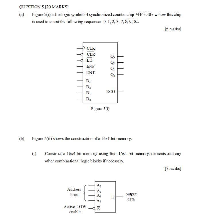
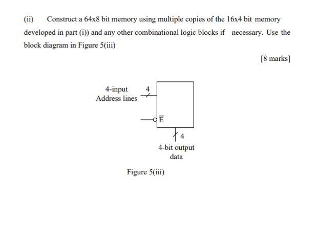
QUESTION 5 [20 MARKS] (a) Figure 5(1) is the logic symbol of synchronized counter chip 74163. Show how this chip is used to count the following sequence: 0, 1, 2, 3, 7, 8, 9, ... [5 marks] CLK CLR LD ENP ENT Qo D D2 RCO D D Figure 5(1) (b) Figure 5(ii) shows the construction of a 16xl bit memory. (i) Construct a 16x4 bit memory using four 16xl bit memory elements and any other combinational logic blocks if necessary. [7 marks] Address lines Az A2 A Ao D output data Active-LOW enable E (ii) Construct a 64x8 bit memory using multiple copies of the 16x4 bit memory developed in part (1)) and any other combinational logic blocks if necessary. Use the block diagram in Figure 5(iii) [8 marks) 4-input Address lines -E 4-bit output data Figure 5(iii) QUESTION 5 [20 MARKS] (a) Figure 5(1) is the logic symbol of synchronized counter chip 74163. Show how this chip is used to count the following sequence: 0, 1, 2, 3, 7, 8, 9, ... [5 marks] CLK CLR LD ENP ENT Qo D D2 RCO D D Figure 5(1) (b) Figure 5(ii) shows the construction of a 16xl bit memory. (i) Construct a 16x4 bit memory using four 16xl bit memory elements and any other combinational logic blocks if necessary. [7 marks] Address lines Az A2 A Ao D output data Active-LOW enable E (ii) Construct a 64x8 bit memory using multiple copies of the 16x4 bit memory developed in part (1)) and any other combinational logic blocks if necessary. Use the block diagram in Figure 5(iii) [8 marks) 4-input Address lines -E 4-bit output data Figure 5(iii)
Step by Step Solution
There are 3 Steps involved in it
Step: 1
Get Instant Access to Expert-Tailored Solutions
See step-by-step solutions with expert insights and AI powered tools for academic success
Step: 2
Step: 3
Ace Your Homework with AI
Get the answers you need in no time with our AI-driven, step-by-step assistance
Get Started